Communication system and alignment method of transcoder

a technology of communication system and transcoder, applied in the direction of substation equipment, network traffic/resource management, wireless commuication services, etc., can solve the problems of signal delay, high cost, and audio signal quality degradation, and achieve high tone quality

Active Publication Date: 2007-02-20
NEC CORP
View PDF4 Cites 32 Cited by
  • Summary
  • Abstract
  • Description
  • Claims
  • Application Information

AI Technical Summary

Benefits of technology

[0019]Another object of the present invention is to provide a communication system in which service degradation, such as delay of connection and / or instantaneous cut-off of sound, caused by insertion of a transcoder when a terminal is switched to a switching node RNC, an alignment method of transcoder and a switching node.
[0020]Another object of the present invention is to provide a communication system in which a procedure for relocation of a switching node is simple, an alignment method of transcoder and a switching node.
[0021]The reason for the insertion of a transcoder in a switching node MSC of a core network into a TrFO connection call at a time of relocation of a switching node RNC is that a RFCI information used with respect to an old switching node RNC is not always used for a new switching node RNC. If the RFCI information for the new switching node on an input side of the inserted transcoder is the same as that used for the old switching node on an output side of the transcoder, AMR data can be transmitted simply without necessity of a format conversion of AMR data (decoding on the input side and coding on the output side). Therefore, it is possible to return to the TrFO connection by bypassing the transcoder.
[0022]The present invention is featured by that, when a transcoder of a switching node MSC of a core network is inserted at a time of relocation of a switching node RNC, the switching node MSC inquires of the switching node RNC of a radio access network about whether or not a setting information of the inserted transcoder can be initialized by using a RFCI information, which is the same on both input and output sides of the transcoder to allow a bypassing of the transcoder, and the transcoder is removed and the system is returned to a TrFO connection when the switching node RNC is initialized such that the RFCI information on the input side of the transcoder becomes the same as that on the output side of the transcoder. Therefore, it is possible to use the TrFO connection, which provides a high tone quality, in a new switching node to which a terminal is moved.

Problems solved by technology

Therefore, distortion of the transmission signal due to the coding / decoding method is accumulated, resulting in a degraded audio signal quality.
If transcoders are inserting into all channels of the switching node MSC, the cost therefor becomes high and a signal delay may occur due to the signal conversions.
In such case, when relocation is performed to a switching node RNC of a different carrier, it may be impossible to continue the TrFO connection since the same RFCI information is not always used.
This is because there is no guarantee that the same RFCI information for the bandwidth-compression as that previously used can be used for a new switching node RNC.
Therefore, when the terminal enters into the area covered by the new switching node RNC and the transcoder in the switching node MSC is inserted, it is necessary to insert at least four coding / decoding devices as mentioned previously and degradation of tone quality can not be avoided.
In this proposal, however, the procedure for shifting the TrFO by inserting / removing the transcoder is complicated, compared with the system in which the negotiation is performed after the re-initialization is performed once.
That is, when a negotiation is performed between the new switching node RNC of the radio access network and the switching node MSC of the core network and the RFCI information is different from that used for the previous TrFO connection, a re-initialization including the remote side switching node RNC becomes necessary, so that the procedure therefor becomes complicated.

Method used


Image

  • Communication system and alignment method of transcoder
  • Communication system and alignment method of transcoder
  • Communication system and alignment method of transcoder

Examples


Embodiment Construction

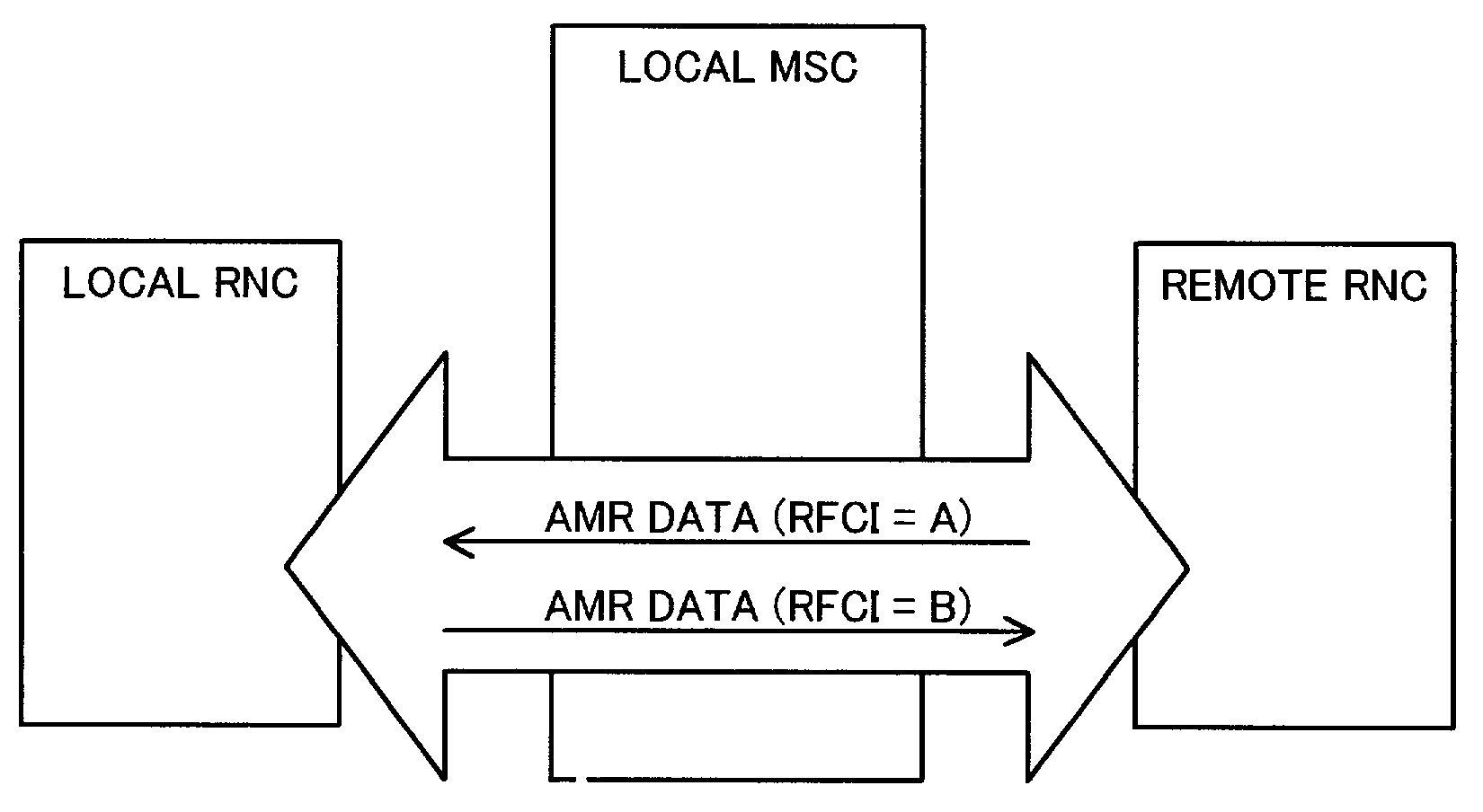
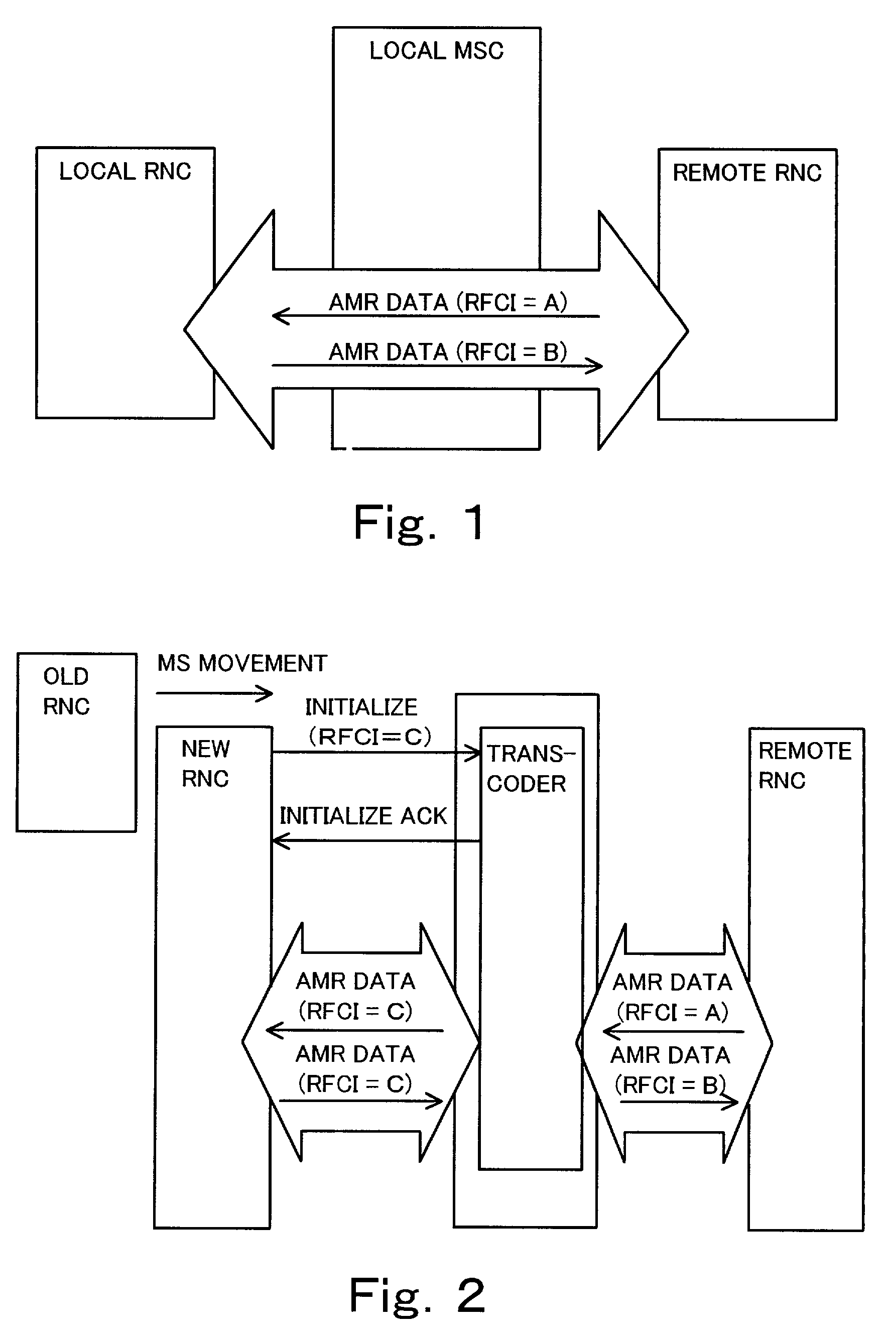
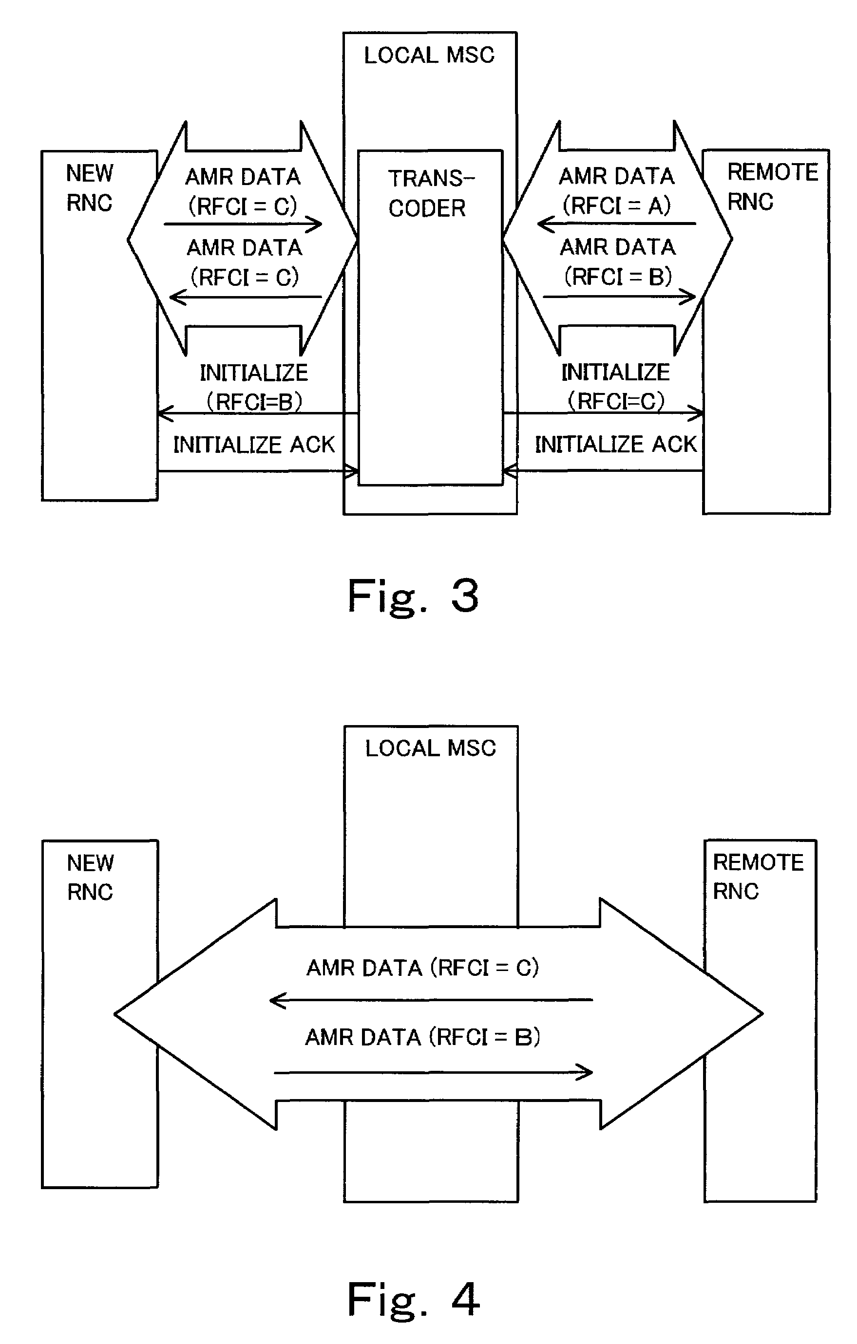
[0045]A transcoder alignment operation according to the present invention will be described with reference to FIGS. 1 to 5, in which FIGS. 1 to 4 shows a transcoder alignment operation for returning to a TrFO operation by performing an inserting / removing operation when a terminal is moved to a new switching node RNC and FIG. 5 is a flowchart of the transcoder alignment operation shown in FIGS. 1 to 4.

[0046]In FIG. 1, a TrFO connection is established between a local switching node RNC and a remote switching node RNC by bypassing a transcoder of a switching node MSC with using a RFCI information A of AMR data in an up link leftward user bit stream in the drawing sheet) and a RFCI information B of AMR data in a down link (rightward user bit stream in the drawing sheet) according to a negotiation between a calling terminal and a called terminal.

[0047]It is assumed here that the calling side terminal is moved to an area covered by a new switching node RNC of a radio access network as sho...


PUM


Abstract

When a terminal is moved to an area covered by a different switching node RNC of a radio access network, degradation of speech quality is prevented by returning a transcoder insertion connection to a transcoder-free-operation connection. When the terminal is moved and the switching node RNC of the radio access network is changed, a relocation is performed by inserting the transcoder, re-confirmation of parameter information of a bandwidth-compression coding system is requested for a local side switching node RNC and a remote side switching node RNC and, when the transcoder can be bypassed according to the confirmation, the transcoder is removed to return to the transcoder-free-operation connection mode.

Description

BACKGROUND OF THE INVENTION[0001]1. Field of the Invention[0002]The present invention relates to an interface between a network for transmitting a bandwidth-compressed signal and a network for transmitting non-bandwidth-compressed signal. Particularly, in an interface between a switching node of a radio access network for transmitting a bandwidth-compressed audio signal and a switching node of a core network for transmitting a non-bandwidth-compressed audio signal opposing to the radio access network in a communication network to which the radio access network and the core network are connected, the present invention relates to an insertion / removal control of a transcoder provided in the switching node of the core network for decoding the bandwidth-compressed audio signal transmitted in the radio access network. The switching node of the radio access network is referred to as RNC (Radio Network Controller). As the switching node of the core network having a transcoder, a MSC (Mobile...

Claims


Application Information

Patent Timeline
Patent Type & Authority Patents(United States)
IPC IPC(8): H04Q7/20H04L29/06H04J99/00H04W28/06H04W36/10H04W88/18
CPCH04W88/181H04W36/10H04W28/06
Inventor TAMURA, TOSHIYUKI
Owner NEC CORP
Why Eureka
Try Eureka