
Method of tracking a track geometry

a track geometry and track technology, applied in the field of tracking a track geometry, can solve the problems of destroying the track geometry and causing problems such as the problem of restoring the geometry after introducing the cleaned ballas

Inactive Publication Date: 2007-02-27
FRANZ PLASSER BAHNBAUMASCHINEN IND GMBH
View PDF9 Cites 20 Cited by
  • Summary
  • Abstract
  • Description
  • Claims
  • Application Information

AI Technical Summary

Benefits of technology

"The present invention provides a method for restoring the geometry of a track after it has been destroyed by the operation of a ballast pick-up device. The method involves measuring the track geometry using two measuring chords and associated sensors, and displacing the rear end point of the second measuring chord until it reaches the desired position. The invention also includes a machine for cleaning ballast supporting a track, which includes a screening car and a track measurement system. The track measurement system allows for the copying of the track geometry for restoration after the reintroduction of cleaned ballast. The invention offers the advantage of being able to copy the track geometry regardless of whether the track section is part of a track curve or a transition curve."

Problems solved by technology

When a ballast cleaning machine excavates the ballast underneath a track, the track geometry is necessarily destroyed.
Restoring that geometry after introducing the cleaned ballast is problematic.

Method used


Image

  • Method of tracking a track geometry
  • Method of tracking a track geometry

Examples


Embodiment Construction

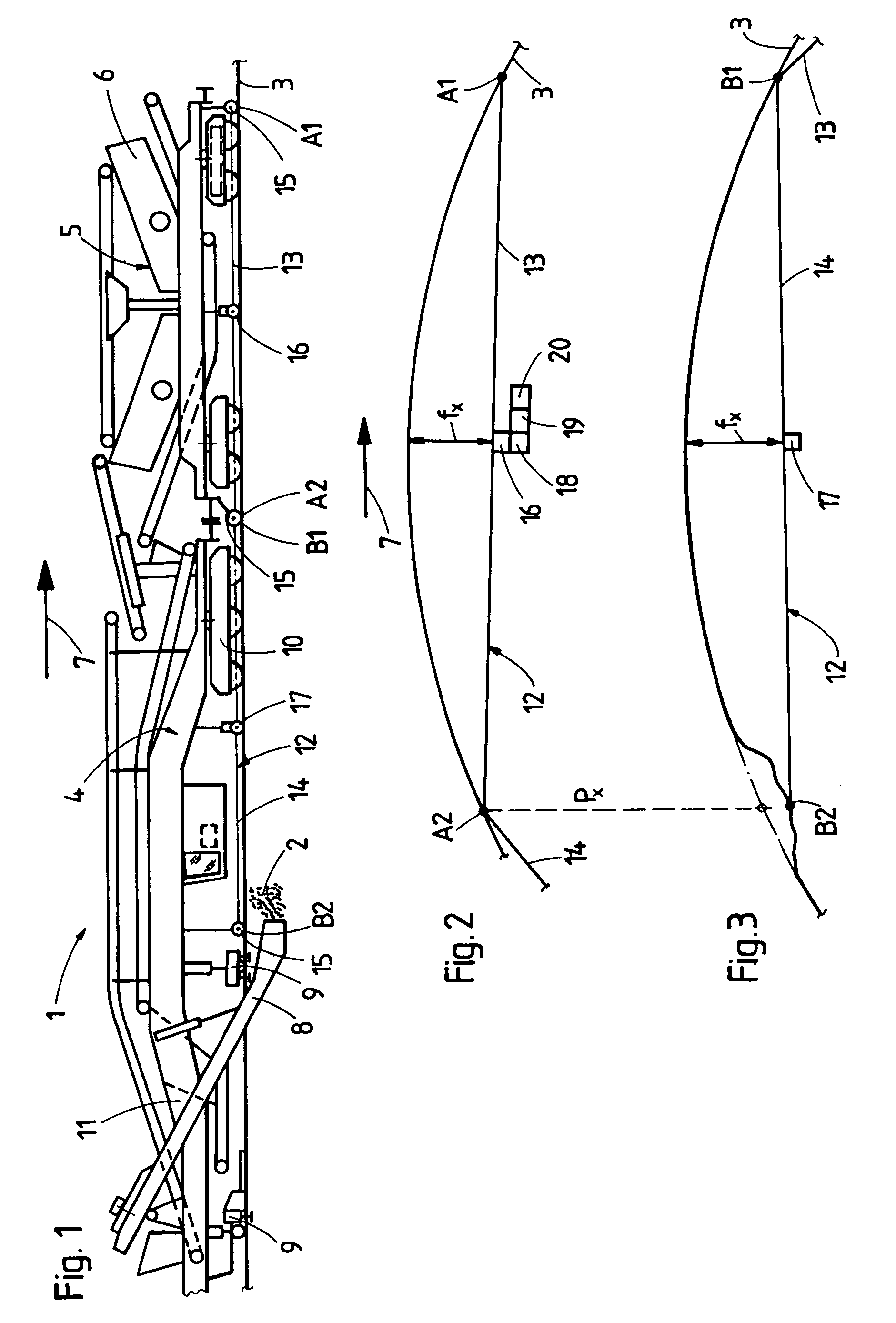
[0014]Turning now to the figures of the drawing and first, particularly, to FIG. 1 thereof, there is shown a cleaning machine 1 for cleaning ballast 2 of a track 3. The machine 1 includes of an excavating car 4 and a screening car 5 coupled thereto. The screening car 4 is equipped with a screening unit 6 for cleaning the excavated ballast. The excavating car 4, following behind the screening car 5 with respect to a working direction 7, comprises a machine frame 11, mobile on the track 3 by means of on-track undercarriages 10, and a ballast pick-up device 8 guided around the track 3, with a first track lifting device 9 being associated with said ballast pick-up device 8. A second track lifting device 9 is connected to the machine frame 11 in front of a rearward on-track undercarriage 10, which is not shown.

[0015]The machine 1 is provided with a track measurement system 12 which consists of a first measuring chord 13—with regard to the working direction 7—and a second measuring chord ...


PUM


Abstract

In a method of tracing a track geometry immediately ahead of a ballast pick-up device of a cleaning machine in a working direction, a first and a second measuring chord are guided on the track by a respective front and rear end point. A versine measured by a first versine sensor of the first measuring chord is stored, in connection with a distance measurement, for registering the rear end point of the first measuring chord as a desired position with respect to a local track point. After the rear end point of the second measuring chord has reached the local track point, the rear end point is displaced until a measurement value corresponding to the stored versine is reached by a second versine sensor, and thus the desired position has been attained.

Description

BACKGROUND OF THE INVENTION[0001]1. Field of the Invention[0002]The present invention relates, in general, to a method of tracing the geometry of a track immediately ahead of a ballast pick-up device, with respect to a working direction, and of restoring said geometry after it has been destroyed by the operation of said ballast pick-up device. The invention also relates to a machine for cleaning ballast.[0003]2. Description of Related Art[0004]A method of the afore-mentioned type is known from U.S. Pat. No. 4,574,704. When a ballast cleaning machine excavates the ballast underneath a track, the track geometry is necessarily destroyed. Restoring that geometry after introducing the cleaned ballast is problematic. According to the prior art method, the position of a first measuring chord—situated ahead of the ballast pick-up device with regard to the working direction—follows the track geometry. This position is used as a reference to guide a second, trailing measuring chord. To that e...

Claims


Application Information

Patent Timeline
Patent Type & Authority Patents(United States)
IPC IPC(8): E01B35/00E01B27/00E01B29/04
CPCE01B35/00
Inventor THEURER, JOSEFLICHTBERGER, BERNHARDWORGOTTER, HERBERT
Owner FRANZ PLASSER BAHNBAUMASCHINEN IND GMBH
Learn More