Fuel transfer coupling

a fuel transfer and coupling technology, applied in the field of couplings, can solve the problems of large volume of gasoline spilled onto the pavement and portions of the vehicle being refueled, immediate health risks to pit crew personnel other than fire hazards, and the issue of tetraethyl lead and related compounds as health hazards to pit crews

Active Publication Date: 2007-02-27
SCHULTZ JR ROBERT L
View PDF3 Cites 12 Cited by
  • Summary
  • Abstract
  • Description
  • Claims
  • Application Information

AI Technical Summary

Problems solved by technology

Since the fuel-carrying capacity of the race car is limited by the rules of racing to be of specific volume, and the capacity of such tanks is not sufficient to enable the racer to complete the entire race on a single tank load of fuel, it is a general requirement of modern automobile racing that drivers must stop their vehicles periodically to have their tanks re-charged with fuel.
However, one of the disadvantages of current re-fueling methods is that large volumes of gasoline are spilled onto the pavement and portions of the vehicle being re-fueled.
A typical volume of fuel lost by spillage in re-fueling operations during the course of a race may be several gallons of fuel, which losses occur primarily when the recharging tank is removed from the inlet conduit.
While pit crews are well-equipped to deal with inadvertent fires that may occasionally occur, there are immediate health risks to pit crew personnel other than the fire hazard.
Since these lead compounds are volatile and since they are known health hazards, the issue of inhalation of tetraethyl lead and related compounds as a health hazard to pit crews is a serious matter.
Another issue for automobiles is the concept of vapor lock.
Eventually, the fuel pump is required to pump fuel from an area of reduced pressure, and, not being designed for such use, a less-than-desired amount of fuel is delivered to the engine, which results in inhibited engine performance.

Method used


Image

  • Fuel transfer coupling
  • Fuel transfer coupling
  • Fuel transfer coupling

Examples


Embodiment Construction

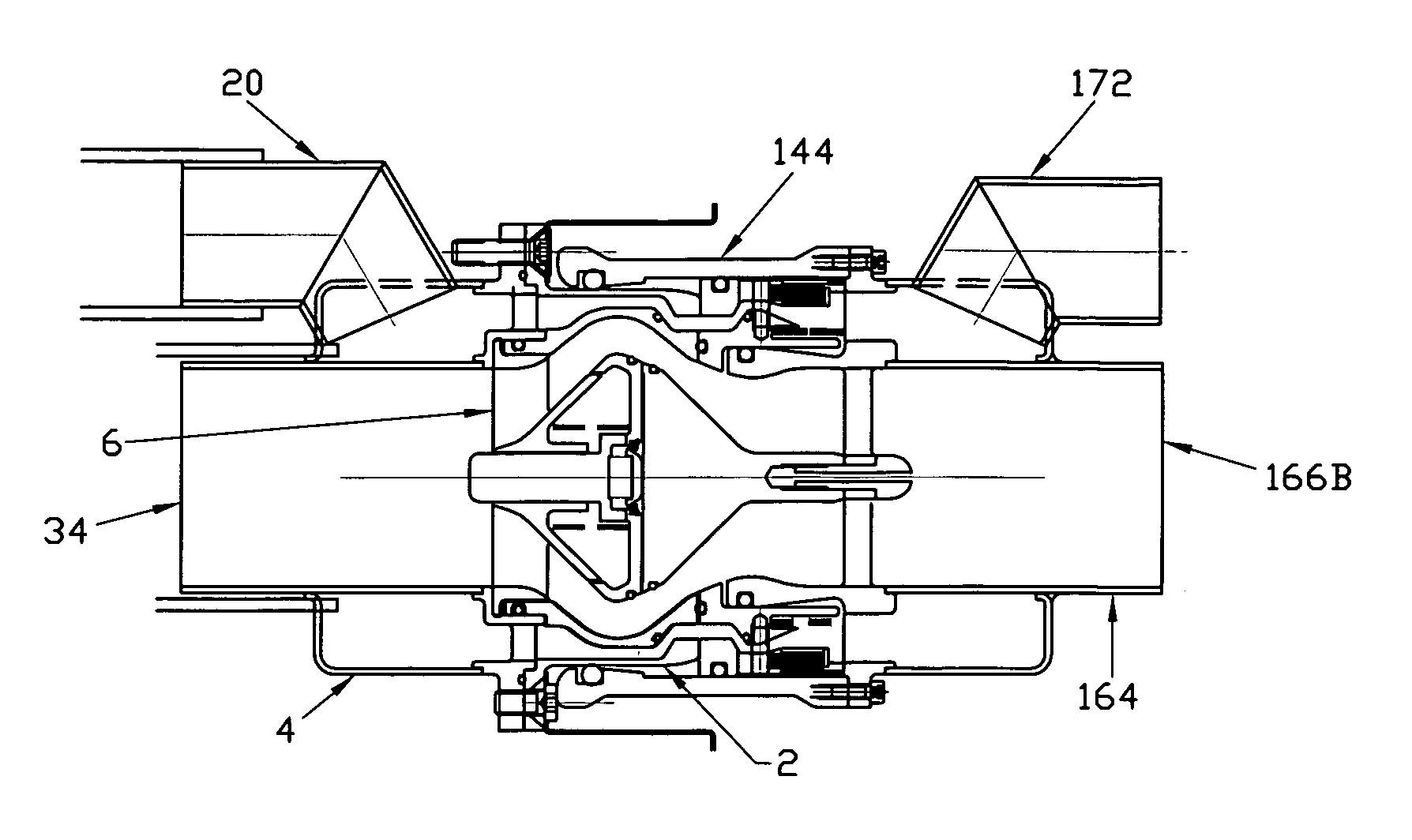
[0074]A fuel transfer coupling according to the present invention comprises an on-board portion which is in fluid contact with the gasoline tank on a motorized vehicle such as a race car, and a remote portion which is in fluid contact with a source of liquid hydrocarbon fuel that is to be delivered to the gasoline tank of the motorized vehicle. The on-board portion may be referred to as the male adapter and the remote portion of the coupling may be referred to as the female adapter, for convenience.

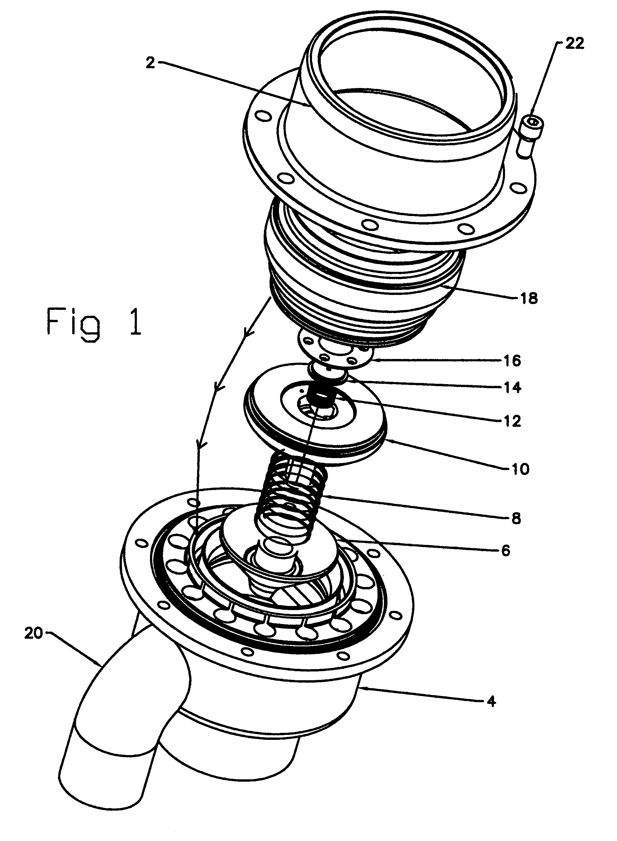
[0075]Referring to the drawings, and initially to FIG. 1 there is shown the on-board portion of a fuel transfer coupling according to the invention in an exploded view, including all of its various components, which are described forthwith.

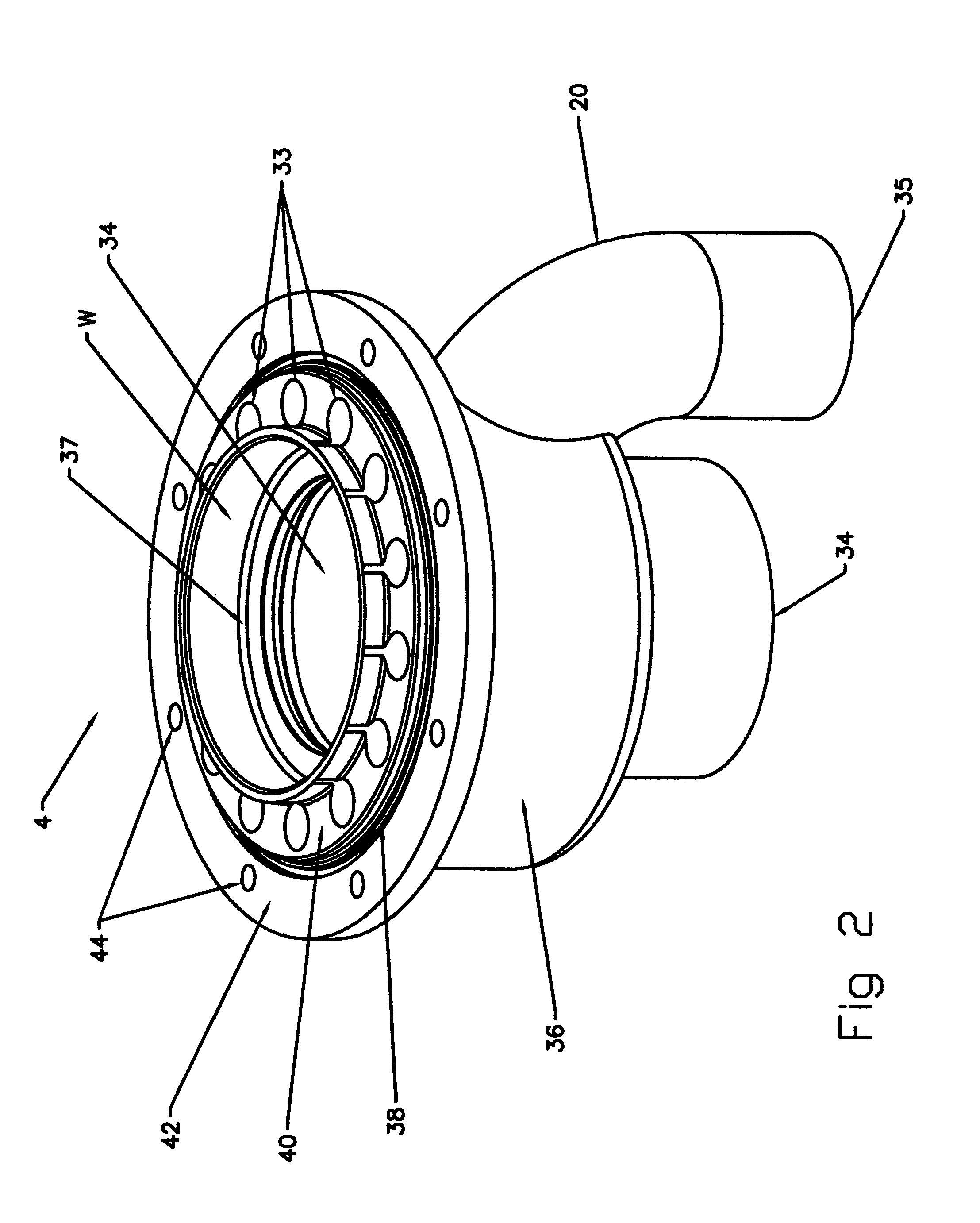
[0076]In FIG. 2 is shown a perspective view of the male adapter base 4. The male adapter base 4 includes a central bore 34 through which fuel is intended to flow. The central bore 34 has a first end portion which is adapted to be connected to the inlet ...


PUM


Abstract

Provided herein are couplings useful in the transfer of liquid fuels from a remote storage reservoir to an on-board fuel tank of a motorized vehicle. There is provided a first coupling which is adapted to be in fluid communication with the interior of a vehicle's fuel tank, and a second coupling which is intended to be in fluid communication with the contents of a remote fuel storage reservoir. The invention also includes a process for charging a fuel reservoir on board of a motorized vehicle from a remote reservoir, wherein the vapor in the fuel reservoir is displaced by an equal volume of fuel delivered from said remote reservoir, and wherein the vapor in said fuel reservoir is simultaneously caused to be transferred to said remote reservoir, thus permitting no escape of the vapor from said fuel reservoir to the surrounding atmosphere. Through use of the present invention, spills of fuel are essentially eliminated, and the escape of vapors from the vehicle's fuel tank are prevented, thus preventing atmospheric hydrocarbon pollution.

Description

CROSS-REFERENCES TO RELATED APPLICATIONS[0001]This application claims the benefit of U.S. Provisional Application No. 60 / 432,162 filed Dec. 10, 2002 the entire contents of which are herein incorporated by reference.TECHNICAL FIELD[0002]This invention relates generally to couplings used in transferring a liquid substance from one reservoir in which a liquid is stored to a second reservoir. More particularly, the invention relates in one embodiment to couplings useful in transferring a liquid hydrocarbon fuel from a storage vessel to an on-board fuel tank inside a motorized vehicle, such as an automobile.BACKGROUND[0003]By the very nature of the utilization of liquid substances such as liquid hydrocarbon fuels, it is frequently necessary to transfer a liquid fuel from a first storage vessel in which it is contained to a second storage vessel. One particular instance in which it is necessary to so transfer a liquid fuel is in the case of re-fueling an automobile during a racing event.[...

Claims


Application Information

Patent Timeline
Patent Type & Authority Patents(United States)
IPC IPC(8): F16L37/32F16L29/04
CPCF16L29/04B67D7/54B67D7/0478Y10T137/87949Y10T137/87957Y10T137/87965
Inventor TILLING, BASIL BSCHULTZ, JR., ROBERT L.
Owner SCHULTZ JR ROBERT L
Why Eureka
Try Eureka