
DC power spraying tool

a power spraying and tool technology, applied in the field of power spraying tools, can solve the problems of operator inability to operate the spraying gun, operator may be in danger, and conventional spraying guns, and achieve the effect of improving the portability of spraying tools

Active Publication Date: 2007-02-27
JINHUA JINSHUN TOOLS
View PDF8 Cites 71 Cited by
  • Summary
  • Abstract
  • Description
  • Claims
  • Application Information

AI Technical Summary

Benefits of technology

[0008]A main object of the present invention is to provide a DC power spraying tool, wherein the spraying tool is powered by a rechargeable battery to provide a direct current as the power source. Therefore, the spraying tool of the present invention is embodied as a cordless spraying tool to enhance the portability of the spraying tool.
[0010]Another object of the present invention is to provide a DC power spraying tool, wherein the spraying tool further comprises a vibration absorbing unit mounted to the pressurized motor for reducing the vibration force caused by the pressurized motor so as to enhance the spraying operation of the spraying tool.
[0011]Another object of the present invention is to provide a DC power spraying tool, wherein the spraying nozzle unit can be simply disassembled from the housing so as to enhance the cleaning process and the repairing purpose of the spraying nozzle unit.

Problems solved by technology

However, the conventional spray gun has several drawbacks.
Therefore, the operator is unable to operate the spray gun under certain circumstances such as an outdoor area that the power source is distance from the operator or a construction area that the electricity is unavailable.
In addition, the operator may be in jeopardy as the operator may trip on the connecting cable.
There is always jeopardy for the operator accidentally getting an electric shock due to the electric leakage of the spray gun.
Another drawback of the conventional spray gun is that the spray nozzle is affixed to the discharging opening of the gun body such that during spraying operation, a vibration force produced by the pressurized motor is exerted to the gun body and the spray nozzle.
Therefore, the vibration of the gun body, which is considered as the noise pollution, will cause the colorant unevenly spraying on the surface.
In addition, due to the structural design of the gun body, the cleaning process and the repairing process of the spray nozzle are complicated and costly.

Method used


Image

  • DC power spraying tool
  • DC power spraying tool
  • DC power spraying tool

Examples


Embodiment Construction

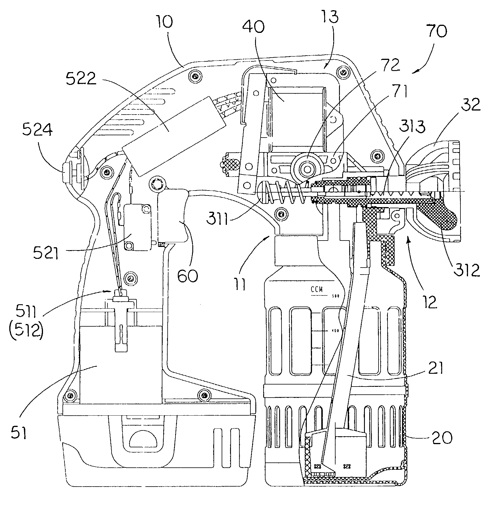
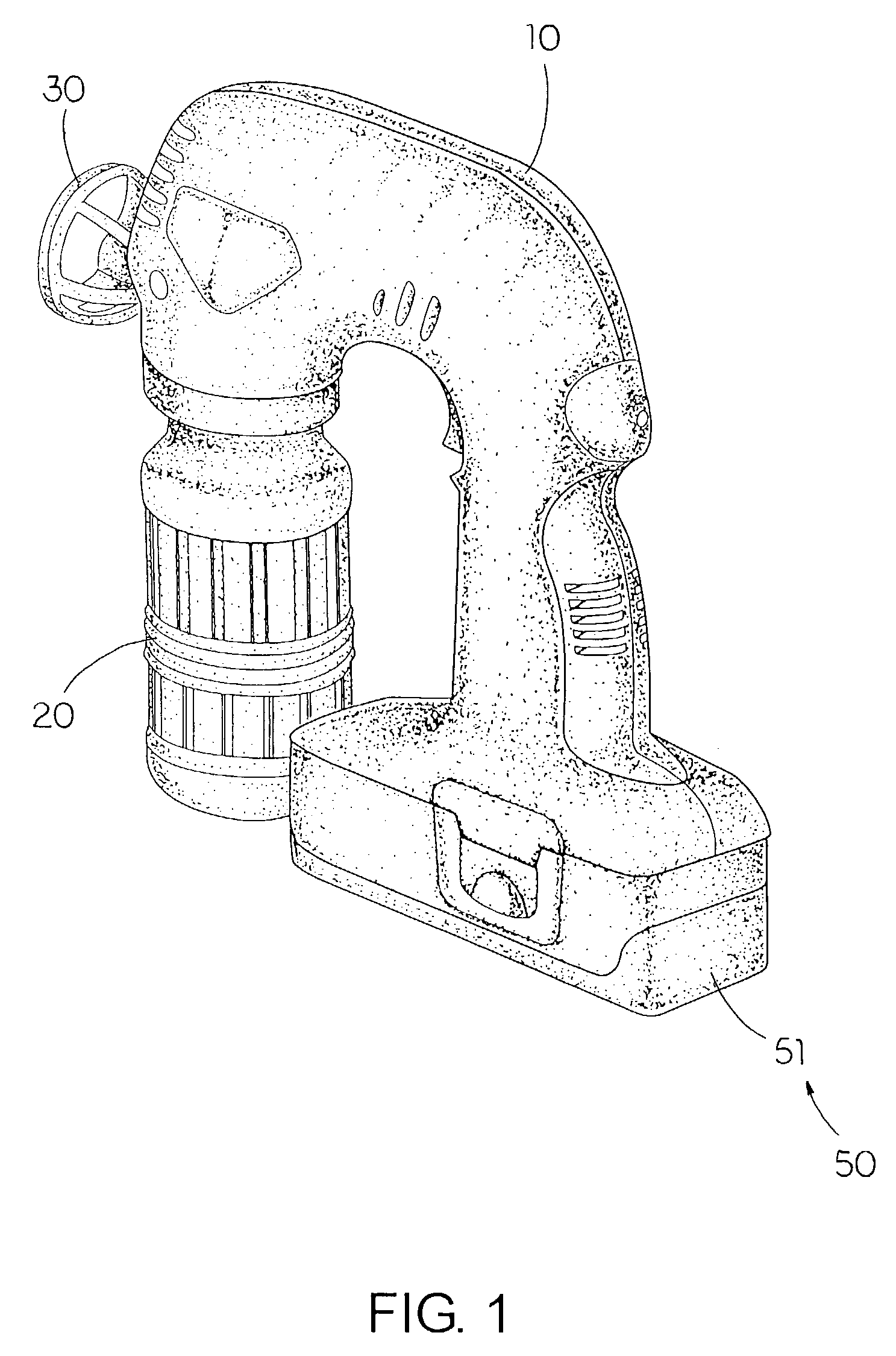
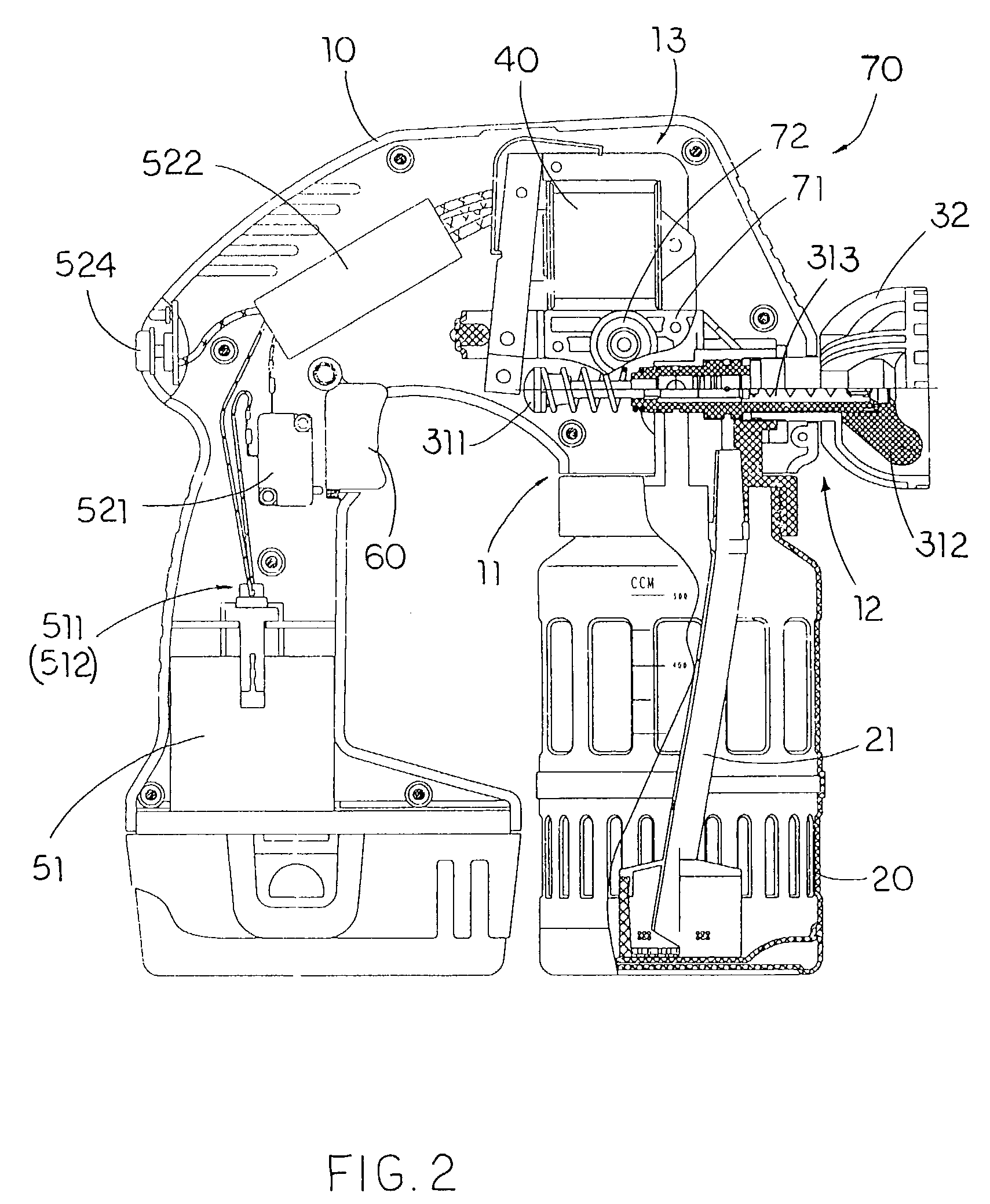
[0024]Referring to FIGS. 1 and 2 of the drawings, a DC power spraying tool according to a preferred embodiment of the present invention is illustrated, wherein the DC power spraying tool comprises a housing 10 having an inlet opening 11, a discharging opening 12 communicating with the inlet opening 11 and a motor cavity 13, a liquid container 20 for containing a liquid colorant therein communicatively connected to the inlet opening 11 of the housing 10.

[0025]The DC power spraying tool further comprises a spray nozzle 30 extended from the discharging opening 12 of the housing 10 to communicate with the liquid container 20, an electric motor 40 supported within the motor cavity 13 of the housing 10 for applying a vacuum pressure on the liquid container 20 to pump the colorant towards the spray nozzle 30, and a DC power source 50 comprising a rechargeable battery 51 supported by the housing 10 for applying a DC current and a control circuitry 52 electrically connected the rechargeable ...


PUM


Abstract

A DC power spraying tool includes a housing having an inlet opening, a discharging opening, and a motor cavity, a liquid container for containing a liquid colorant therein communicatively connected to the inlet opening of the housing, a spray nozzle extended from the discharging opening of the housing to communicate with the liquid container, and an electric motor supported within the motor cavity of the housing for applying a vacuum pressure on the liquid container to pump the colorant towards the spray nozzle. A DC power source includes a rechargeable battery supported by the housing for applying a DC current and a control circuitry electrically connected the rechargeable battery with the electric motor for transforming the DC current to an impulse current so as to drive the electric motor to operate.

Description

BACKGROUND OF THE PRESENT INVENTION[0001]1. Field of Invention[0002]The present invention relates to a spraying tool, and more particularly to a DC power spraying tool, wherein the spraying tool is powered by a rechargeable battery to provide a direct current as the power source, so that the spraying tool is embodied as a cordless spraying tool to enhance the portability of the spraying tool.[0003]2. Description of Related Arts[0004]A conventional spray gun generally comprises a gun body having a discharging opening operatively connected to a spray nozzle and an inlet opening, a liquid reservoir for containing a colorant therein communicatively connected with the inlet opening of the gun body, and a pressurized motor electrically connected to a power source for pumping the colorant from the liquid reservoir on a surface through the spray nozzle. However, the conventional spray gun has several drawbacks.[0005]When the spray gun is electrically connected to the power source through a ...

Claims


Application Information

Patent Timeline
Patent Type & Authority Patents(United States)
IPC IPC(8): B05B9/03B05B9/08
CPCB05B9/0861
Inventor YE, ZHANG GENZHOU, HU SU
Owner JINHUA JINSHUN TOOLS
Learn More