Buckling structure and an electrical connector element using the same

a technology of buckling structure and electrical connector, which is applied in the direction of coupling parts engagement/disengagement, testing/measuring connectors, coupling device connections, etc., can solve the problems of easy breakage of wedged hooks, increased manufacturing costs, and inability to mount the absorbed cover on the metal cover

Inactive Publication Date: 2007-02-27
LOTES
View PDF6 Cites 20 Cited by
  • Summary
  • Abstract
  • Description
  • Claims
  • Application Information

AI Technical Summary

Benefits of technology

[0005]One particular aspect of the present invention is to provide a buckling structure. When the buckling structure is assembled, the absorbed cover is not damaged.
[0009]The buckling structure and an electrical connector element using the same increases the spring force of the wedged-hook. Therefore, the absorbed cover is not damaged during the assembly process.

Problems solved by technology

Because the absorbed cover is installed on the metal cover, the absorbed cover cannot be assembled onto the metal cover if the structure is modified.
The manufacturing cost is therefore increased.
Furthermore, due to the inadequate spring force of a wedged-hook located on the absorbed cover, the wedged-hook is easily broken so as to destroy the absorbed cover after the wedged-hook is used many times.

Method used


Image

  • Buckling structure and an electrical connector element using the same
  • Buckling structure and an electrical connector element using the same
  • Buckling structure and an electrical connector element using the same

Examples


Embodiment Construction

[0018]The electrical connector element of the present invention is illustrated by referring to the attached diagrams and the preferred embodiment.

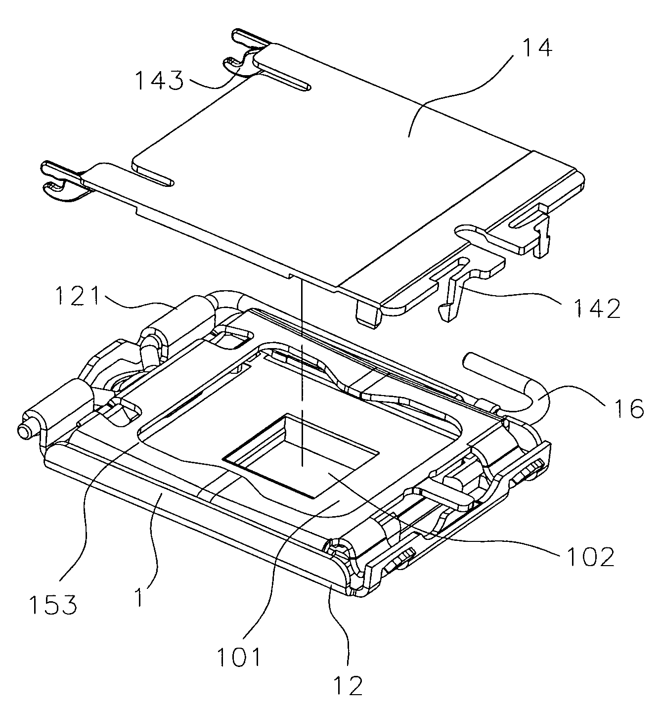
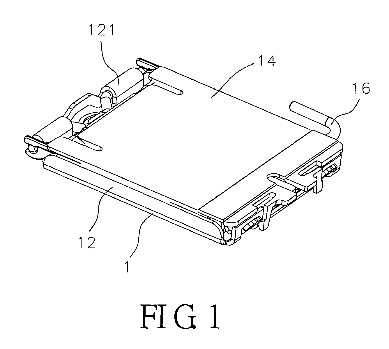
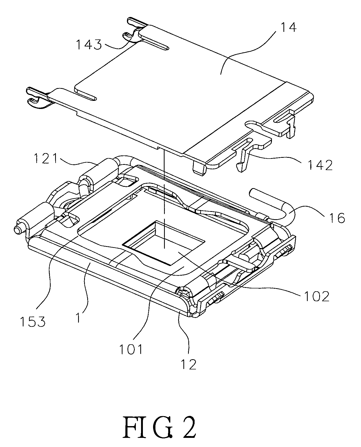
[0019]Reference is made to FIGS. 1 to 4. The electrical connector element of the present invention is used for connecting with a chip module (not shown in the figure). The electrical connector element includes an electrical connector 1 and an absorbed cover 14 assembled on the electrical connector 1. The electrical connector 1 includes an insulating body 10, conducting pins (not shown in the figure), and a buckling base 12. At two ends of the buckling base 12, a cover body 15, used for pressing the chip module, and a rod 16, used for pressing the cover body 15 onto the buckling base 12, are pivoted.

[0020]On the insulating body 10, there is a carrying part 101 for carrying the chip module (not shown in the figure). On the carrying part 101, there are a plurality of receiving holes (not shown in the figure) for receiving the conducting pins ...


PUM


Abstract

A buckling structure includes a buckling part having a buckling point. There is a waving point located in the inside of the buckling point. The buckling point rotates with the waving point to be operated between a buckling status and an opening status. An electrical connector element includes an electrical connector and an absorbed cover assembled on the electrical connector. The absorbed cover has a first wedged-hook that can wedge and fasten to the electrical connector. The first wedged-hook includes a buckling part having a buckling point. There is a waving point located in the inside of the buckling point. The buckling point rotates with the waving point to be operated between a buckling status and an opening status.

Description

BACKGROUND OF THE INVENTION[0001]1. Field of the Invention[0002]The present invention relates to a buckling structure and an electrical connector element using the same.[0003]2. Description of the Related Art[0004]An electrical connector is used for linking a chip module with a circuit board. It is usually composed of a metal base, a metal cover, a rod, and an insulating body receiving a plurality of conducting pins. The metal base of the electrical connector has a square frame structure and the insulating body is received in the metal base. Via the conducting pins in the insulating body (or solder balls under the conducting pins), the electrical connector is assembled on the circuit board using a welding method. In order to assemble the electrical connector automatically, a vacuum-absorbing device is used for absorbing the electrical connector onto the circuit and making the pins on the electrical connector align to the welding holes or conducting flakes. Then, the electrical conne...

Claims


Application Information

Patent Timeline
Patent Type & Authority Patents(United States)
IPC IPC(8): H01R13/62
CPCH01R12/88H01R2201/20
Inventor JU, TED
Owner LOTES
Why Eureka
Try Eureka