Double function-hand operated meat tenderizer

a meat tenderizer and hand-operated technology, applied in meat tenderising, butchering, piercing-based meat tenderising, etc., can solve the problems of high operating cost, loss of taste in meat, loss of natural juice of meat, etc., and achieve the effect of convenient and fast disassembly of the tenderizer

Active Publication Date: 2007-02-27
GOROWSKI VICTOR
View PDF7 Cites 14 Cited by
  • Summary
  • Abstract
  • Description
  • Claims
  • Application Information

AI Technical Summary

Benefits of technology

[0010]It is therefore an object of the present invention to provide a double function and hand operated meat tenderizer that may be used by restaurants, but is also suitable for household use with maximum convenience.
[0012]It is a further object of the present invention to provide a double function meat tenderizer which tenderizes and pierces the meat simultaneously while preventing the tenderizer from slipping out of the user's hand or meat during the process of meat tenderization.
[0013]Another still further object of the present invention is to provide a double function meat tenderizer by pounding or surface treating of the meat using evenly laid-out protruding teeth on the bottom of a movable comb.
[0014]Still another object is to provide a meat tenderizer which is easy and fast to disassemble the tenderizer for cleaning or replacement of the blades.

Problems solved by technology

While these processes have been somewhat successful on the market, two of the most important drawbacks in the chemical tenderizing method are high operating costs and loss of taste in the meat.
The mechanical-type tenderizing method, that is based on the pounding of the surface of the meat with a tenderizing mallet not only cause loss of natural juices of the meat, but also tend to create sinewy lumps.
Further, the handle and the guiding movable plate of the meat tenderizer using a plurality of blades are easy to slip out of the user's hand or meat during the process of tenderizing the meat which was very dangerous for the user due to the sharp blades.
In order to clean or replace the blades, the user needed to disassemble the tenderizer, but in certain cases the cleaning or the replacement of the blades of these tenderizers was quite complicated.

Method used


Image

  • Double function-hand operated meat tenderizer
  • Double function-hand operated meat tenderizer
  • Double function-hand operated meat tenderizer

Examples


Embodiment Construction

[0022]Hereinafter, a preferred embodiment according to the present invention will be described with reference to the accompanying drawings. In the following description of the present invention, a detailed description of known functions and configurations incorporated herein will be omitted when it may obscure the subject matter of the present invention.

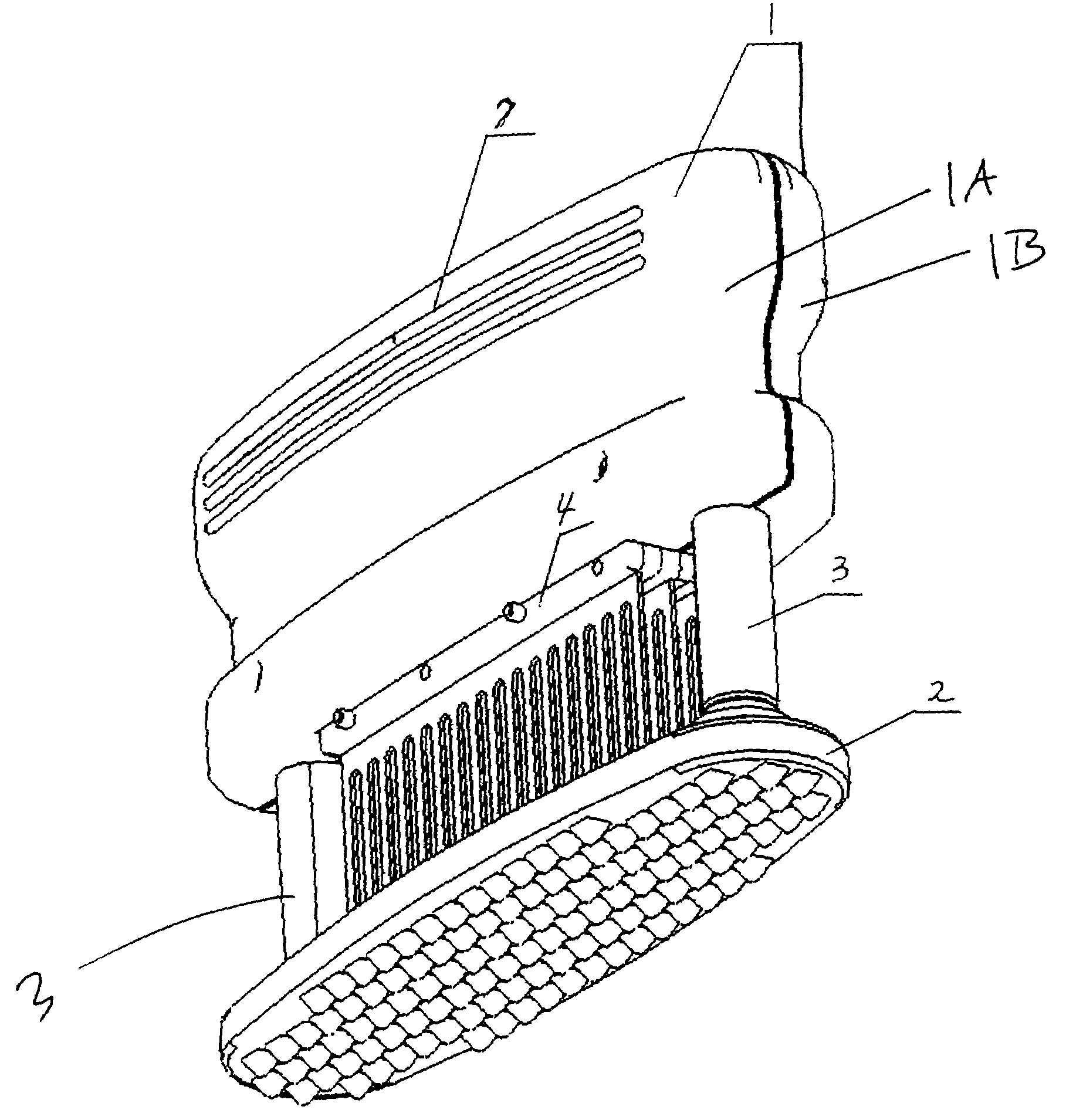
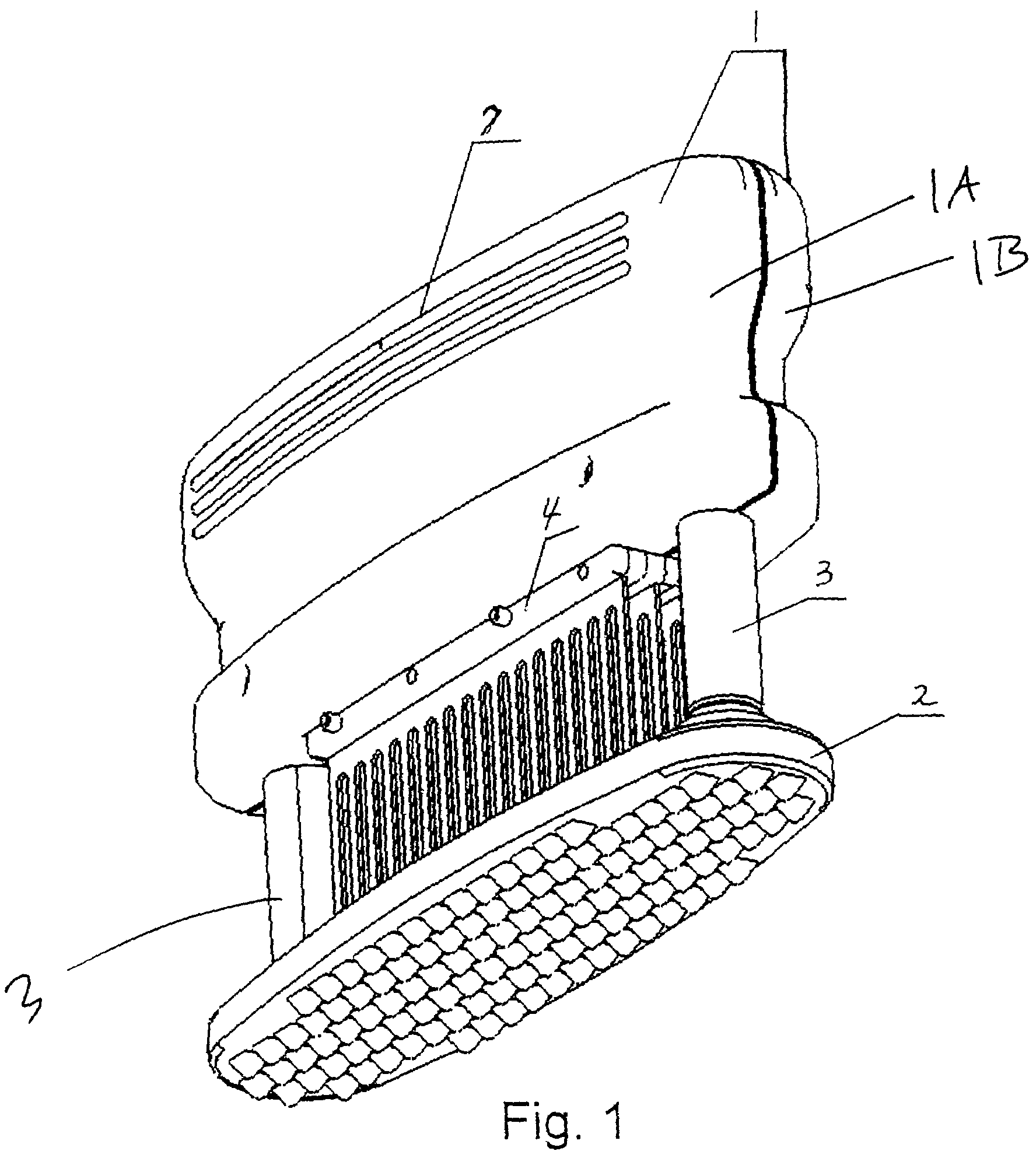
[0023]The present invention provides an esthetic effect through the original and individual shape of exterior surfaces and lines of intersection with the visual combination of the housing material with the stainless steel blades.

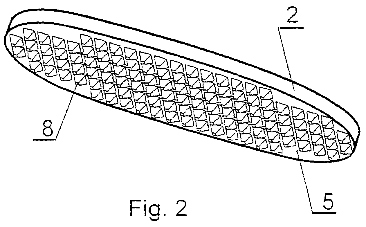
[0024]As shown in FIGS. 1 and 3, a double function-hand operated meat tenderizer according to the preferred embodiment of the present invention includes a handle 1 being formed of two components 1A and 1B, a blade assembly 4 being detachably mounted between the two components 1A and 1B of the handle 1, at least two columns 3, being supplied and operatively connected to the handle 1, and a comb 2 being mounted...


PUM


Abstract

Disclosed is a double function-hand operated meat tenderizer according to the preferred embodiment of the present invention includes a handle being formed of two components, a blade assembly being detachably mounted between the two components of the handle, a plurality of columns where upper ends of the columns are mounted on the handle, and a comb being mounted on lower ends of the columns for being slidably movable toward and away from the handle. The comb has plurality of flow-through slots and protruding teeth extending from a bottom surface of the comb.

Description

PRIORITY[0001]This application claims priority to an application entitled “Meat Tenderizing Machine” filed in The Patent Office of the Republic of Poland on Nov. 15, 2003 and assigned Serial No. P363464 and to a United States Provisional Application entitled “Double Function-Hand Operated Meat Tenderizer” filed on Jul. 2, 2004 and assigned U.S. Provisional Application No. 60 / 584,989, both contents of which are incorporated herein by reference.BACKGROUND OF THE INVENTION[0002]1. Field of the Invention[0003]The present invention relates to a meat tenderizer, and more particularly relates to a double function-hand operated meat tenderizer.[0004]2. Description of the Related Art[0005]According to generally accepted standards in the quality and tenderization of meats for consumption, the meat is preferably matured for a period of three weeks before it is allowed onto the market to be sold. During the maturation process, the connective tissue and meat react with natural enzymes and bacter...

Claims


Application Information

Patent Timeline
Patent Type & Authority Patents(United States)
IPC IPC(8): A22C9/00
CPCA22C9/008
Inventor GOROWSKI, VICTOR
Owner GOROWSKI VICTOR
Why Eureka
Try Eureka