Support arm for cardiac surgery

Inactive Publication Date: 2007-02-27
GENESEE BIOMEDICAL
View PDF22 Cites 106 Cited by
  • Summary
  • Abstract
  • Description
  • Claims
  • Application Information

AI Technical Summary

Benefits of technology

[0017]The present invention is directed toward an improved platform or support arm from which to base coronary artery surgery, including beating heart stabilization. The invention is intended to provide the surgeon with a versatile, configurable, rigid base to which task specific accessories may be attached. Designed to be reusable, the present invention also offers a lower cost opportunity per procedure.
[0018]The present invention incorporates a majority of reusable components, with only certain heart contact component used in coronary artery surgery being disposable. This arrangement combines disposable product economy with high quality and highly effective reusable devices, leading to significant cost reduction per procedure for the hospital. Multiple choice disposable heart contact members allows the surgeon to choose the optimum attachment to suit the procedure and anatomy. Furthermore, the extensive adjustability of the device, including the ability to vary the length of the articulated arm, vary the orientation of the contact member, rotate the contact member axially of the articulated arm axis, and rotate the articulated arm about the base, allows the surgeon access to the entire heart, including the entire external surface of the heart. A desired configuration of all the adjustable elements can then be fixed securely with a single control element, namely the knob at the proximal end of the articulated support arm. A clutch mechanism in the knob prevents over stressing of the components. The stainless steel construction of the device along with

Problems solved by technology

It soon became apparent to many cardiac surgeons that a minimal incision (usually a thoracic as opposed to a sternal incision) was both surgically inadequate, and it resulted in increased post-operative pain as compared with a midline sternotomy.
Hence, this procedure fell out of favor after a couple of years.
In some studies overall hospital stay and hence treatment cost did fall, although in other studies this was not found to be the case.
While the rigid metal arms are fairly stiff, they are not suitable for accessing the proximal obtuse marginal branches of the circumflex coronary arteries on posterior part of the epicardium or the distal circumflex arteries.
Because Young's Modulus of plastic is low compared to that of stainless steel,

Method used


Image

  • Support arm for cardiac surgery
  • Support arm for cardiac surgery
  • Support arm for cardiac surgery

Examples


Embodiment Construction

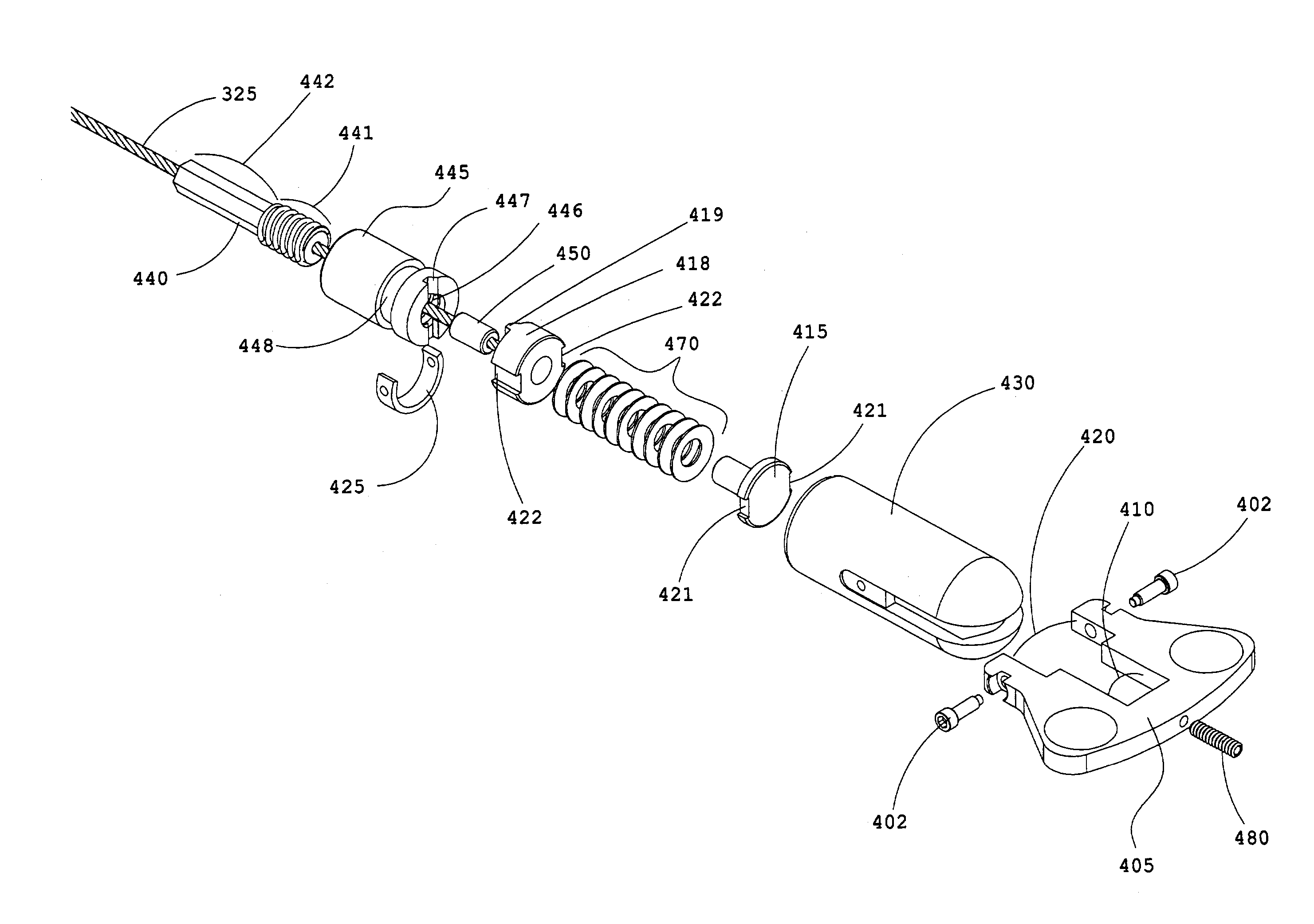
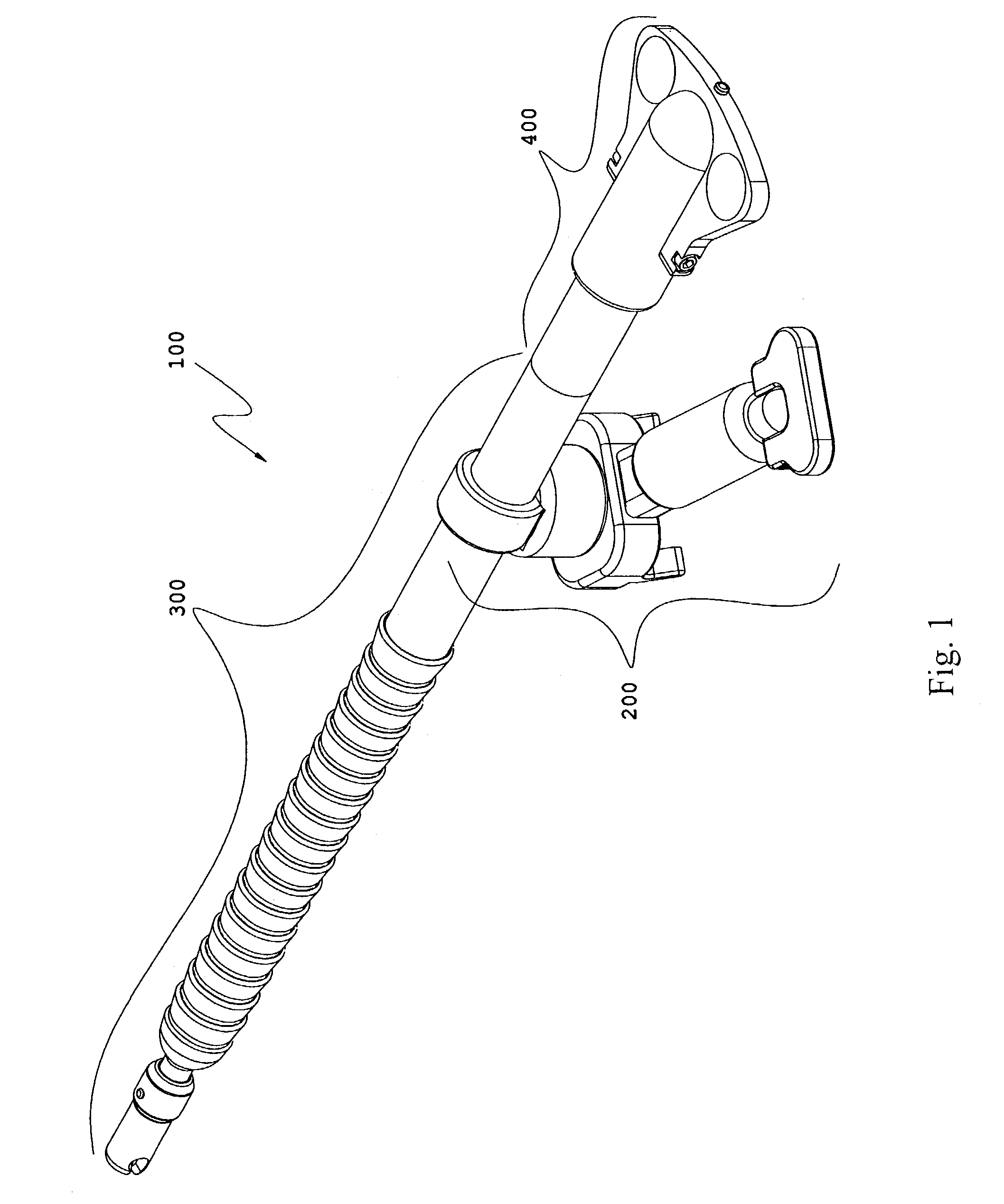
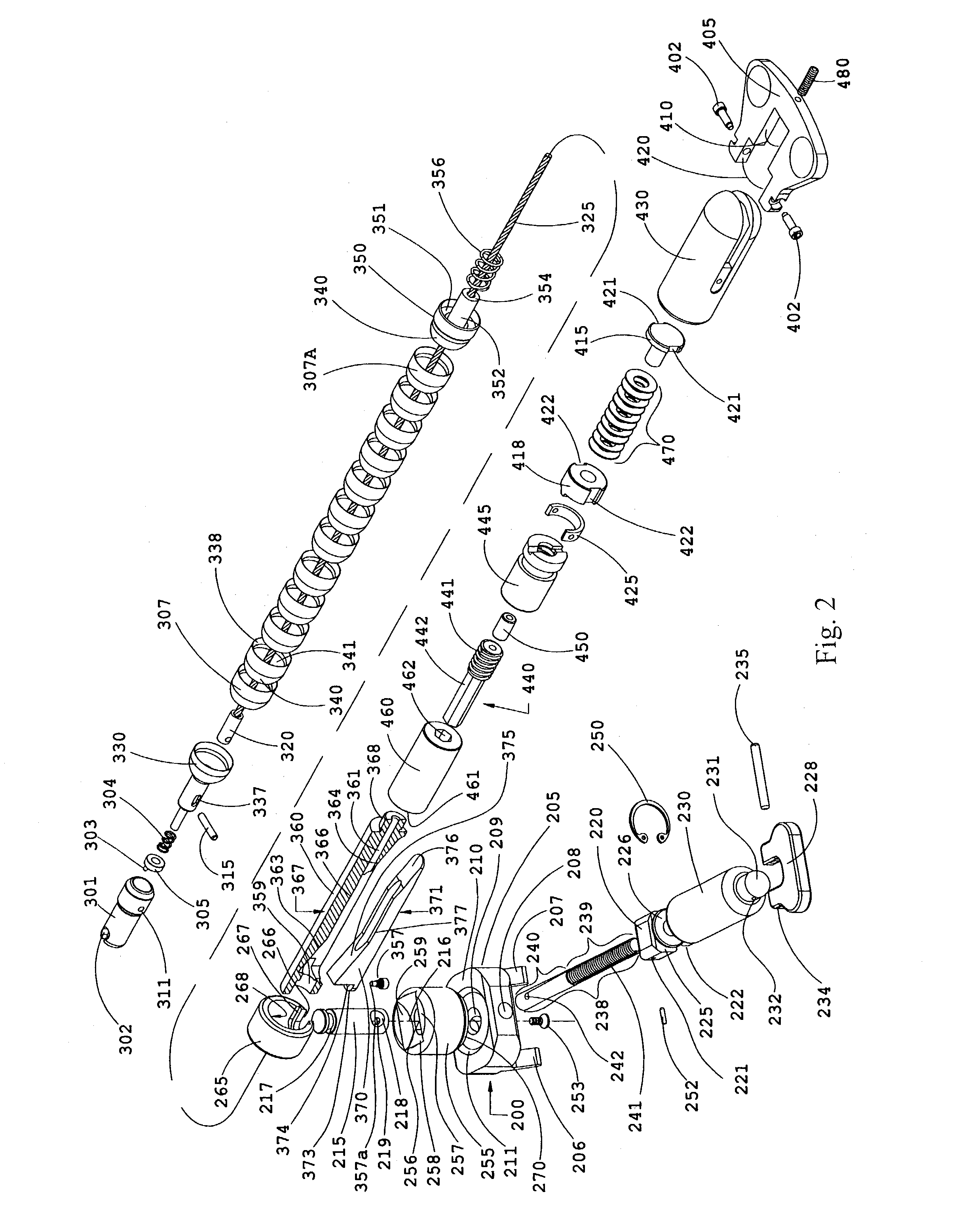
[0034]A support arm assembly 100 is comprised of a clamp base 200 an articulated arm 300 and a locking mechanism assembly and torque limiting mechanism 400.

[0035]Referring to FIG. 2, the clamp 200 base provides a mechanism for attachment by clamping onto the arms or rack of common or specialized sternal retractors (as illustrated in FIG. 9). The clamp base 200 includes a foundation 205 having a pair of spaced grip fingers 206207, a transverse cylindrical recess 208 at right angles to fingers, not shown, and a vertical central through hole 209. The upper face 210 has tapered recess 211. Opposing clamp base foundation 205 is clamp hook220 having a grip finger 222 which cooperates with fingers 206, 207 for gripping onto the retractor features. The clamp base 200 also includes a pivot 215 defining a pivotal axis 216 for the articulating arm to be radially positioned relative to clamp base 200. In the present embodiment, the pivot axis is oriented vertically relative to the clamp base fo...


PUM


Abstract

A support arm assembly for assisting in the performance of cardiac surgery has an articulated arm movable axially of a support base and rotatable relative to the support base. A distal end of the articulated arm receives a contact member and the contact member is moveable relative to the distal end. A surgeon may configure the support arm assembly to contact a desired portion of a heart and fix the articulated arm, its axial position, its rotated position and the orientation of the contact member with a single control.

Description

RELATED APPLICATIONS[0001]This application claims priority from U.S. Provisional Patent Application Ser. No. 60 / 351,986, filed Jan. 23, 2002, entitled “Support Arm for Cardiac Surgery.”TECHNICAL FIELD[0002]The present invention relates generally to surgical tools including surgical tools for cardiac surgery, and more specifically to surgical tools used in conjunction with Coronary Artery Bypass surgery, both the on-pump and the off-pump variety.BACKGROUND ART[0003]Off-Pump Coronary Artery Bypass (OPCAB) has evolved since about 1990, following the pioneering work done in North America by Ankeney in the period 1970–75, Akins et al. 1979, and Fanning et al. 1979–1992 in the U.S, and by Trapp & Bisarya in the early 1970's in Canada. In South America other pioneering was done by Benetti (1978–85) in Argentina and Buffolo (1981–85) in Brazil. Generally the anastomotic site was immobilized with stay sutures, such as the technique described by Trapp & Bisarya, who encircled the anastomotic ...

Claims


Application Information

Patent Timeline
IPC IPC(8): A61B1/32A61B17/00A61B17/02A61B17/28A61B19/00
CPCA61B17/0206A61B19/26A61B2017/00243A61B2019/266A61B2017/2905A61B2019/268A61B2017/0243A61B90/50A61B2090/031A61B2090/508A61B2090/571
Inventor NGUYEN, HIEU CONGWRIGHT, JOHN THOMAS MATTHEWSKINKLE, DAVID WILLIAM
Owner GENESEE BIOMEDICAL
Why Eureka
Try Eureka