Micro-helix antenna and methods for making same

a micro-helix antenna and antenna technology, applied in the field of helical antennas and methods for making helical antennas, can solve the problem that the diameter of the antenna is generally too large to allow further compression

Inactive Publication Date: 2007-02-27
SCIPERIO
View PDF43 Cites 141 Cited by
  • Summary
  • Abstract
  • Description
  • Claims
  • Application Information

AI Technical Summary

Problems solved by technology

However, such antennas generally are too large in diameter to allow further compression.

Method used


Image

  • Micro-helix antenna and methods for making same
  • Micro-helix antenna and methods for making same
  • Micro-helix antenna and methods for making same

Examples


Embodiment Construction

[0018]The present invention is directed to the fabrication of antennas that are significantly smaller than their established solid-conductor counterparts, such as the half-wave linear dipole. By using a “micro-helix” conductor element, significant size reductions may be achieved. Micro-helix conductors of the present invention may be used in straight-wire antennas (linear dipoles), stochastic or other meandering line antennas, spiral antennas, and other compression schemes.

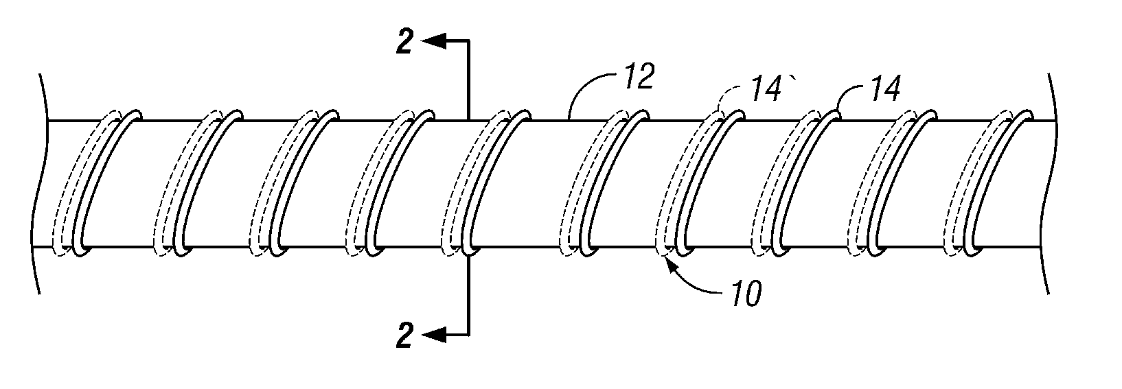
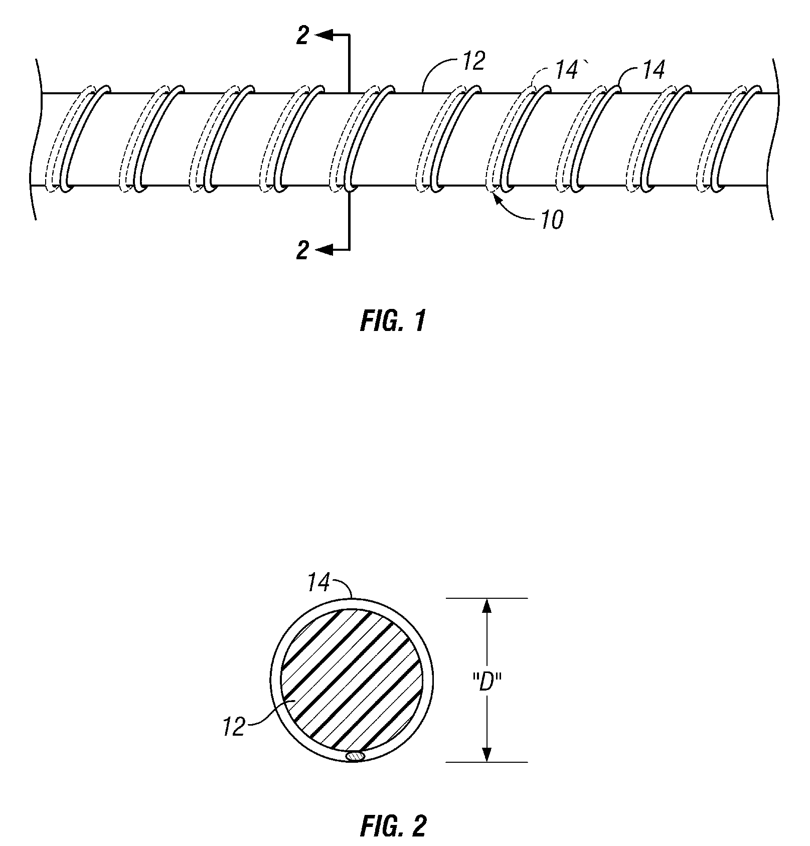
[0019]Turning now to the drawings in general and to FIG. 1 in particular, there is shown therein an antenna constructed in accordance with the present invention and designated generally by the reference numeral 10. The antenna 10 preferably comprises an elongate dielectric core 12 and at least a first helically-shaped conductor 14 disposed about the core.

[0020]The dielectric core 12 preferably is flexible but relatively nonelastic to allow further compression as described in more detail below. In the embodiment of...


PUM


Abstract

A micro-helix antenna. The antenna comprises a helically-shaped conductive element disposed on a dielectric core. The diameter of the helix formed by the conductive element is very small relative to the wavelength of the antenna, preferably no more than about 1 / 100th of the wavelength. Having such a small diameter, this micro-helix antenna can be further compressed into two- and three-dimensional shapes, such as spirals, helices and meandering or stochastic patterns. The micro-helix antenna can be created by pressing a fine wire into a helical shape. Alternately, the helical conductor can be formed by a laser ablation process or laying down the helical shape using a direct-write process.

Description

DESCRIPTION[0001]This application claims the benefit of provisional application Ser. No. 60 / 576,378, filed Jun. 2, 2004 entitled Micro-Helix Antenna, the contents of which are hereby incorporated by reference.FIELD OF THE INVENTION[0002]The present invention relates generally to helical antennas and methods for making helical antennas.BACKGROUND OF THE INVENTION[0003]There is a growing need in many technical fields to form smaller antenna elements. One technique often employed in antenna design is to embed an inductor within the antenna to add electrical length to an otherwise size-reduced antenna, making the antenna behave as if it were longer. This technique is often employed in standard CB-type antennas to provide length reduction and impedance matching. Conventional helical antennas typically utilize helix diameters that are a significant fraction of a wavelength. However, such antennas generally are too large in diameter to allow further compression. Thus, there is a need for a...

Claims


Application Information

Patent Timeline
Patent Type & Authority Patents(United States)
IPC IPC(8): H01Q1/36H01Q7/00H01Q7/08H01Q11/08
CPCH01Q1/362H01Q11/08H01Q7/08H01Q7/00
Inventor WILHELM, MICHAEL J.TAYLOR, ROBERT M.SALISBURY, RYAN T.
Owner SCIPERIO
Why Eureka
Try Eureka