Digital micro-mirror device having improved contrast and method for the same

a digital micromirror and contrast technology, applied in the field of optical processing devices, can solve the problems of lowering the risk of damage to the dmd, and achieve the effect of improving contrast and reducing reflection

Active Publication Date: 2007-02-27
TEXAS INSTR INC
View PDF2 Cites 73 Cited by
  • Summary
  • Abstract
  • Description
  • Claims
  • Application Information

AI Technical Summary

Benefits of technology

[0004]According to one embodiment of the present invention, a digital micro-mirror device having improved contrast and a method for the same are provided. The digital micro-mirror device comprises a plurality of current-carrying conductors on an upper surface of a substrate, each current-carrying conductor having an upper surface; a low-reflectivity metal disposed upon the upper surfaces of the current-carrying conductors; and first and second micro-mirrors forming an aperture above the substrate. The low-reflectivity metal disposed upon on the upper surfaces of the current-carrying conductors reduces the reflection of light received through the aperture by the current-carrying conductors.
[0005]A technical advantage of some embodiments of the present invention includes a digital micro-mirror device having improved contrast over conventional DMDs. Rather than leaving the highly-reflective current-carrying conductors on the upper surface of the substrate exposed, particular embodiments of the present invention cover these conductors with a low-reflectivity metal that reduces the reflection of light off the superstructure of the DMD.
[0006]Another technical advantage of some embodiments of present invention is that the low-reflectivity metals used tend to form ionic compounds when exposed to the compounds in the headspace of the DMD. These ionic compounds typically have lower partial pressures than covalent compounds, lowering the risk of damage to the DMD due to excessive pressures in the headspace.
[0007]Yet another technical advantage of some embodiments of the present invention is that the low-reflectivity metal used in the DMD has a naturally low absorption coefficient, allowing the low-reflectivity metal to be used in a multilayer stack structure where the metal is at least partially transmissive. In some embodiments, these multilayer stack structures may have reflectivities even lower than those of a single-layer structure of infinite thinkness.

Problems solved by technology

These ionic compounds typically have lower partial pressures than covalent compounds, lowering the risk of damage to the DMD due to excessive pressures in the headspace.

Method used


Image

  • Digital micro-mirror device having improved contrast and method for the same
  • Digital micro-mirror device having improved contrast and method for the same
  • Digital micro-mirror device having improved contrast and method for the same

Examples


Embodiment Construction

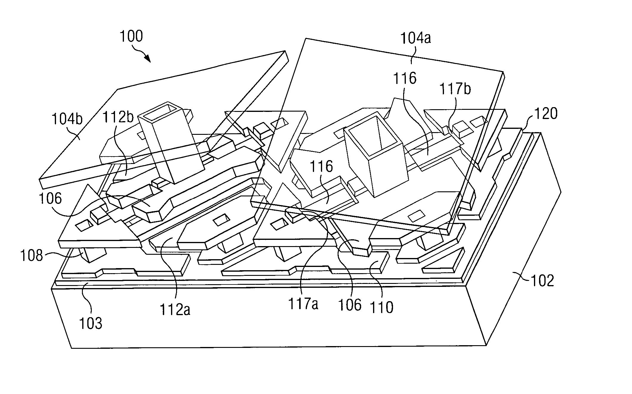
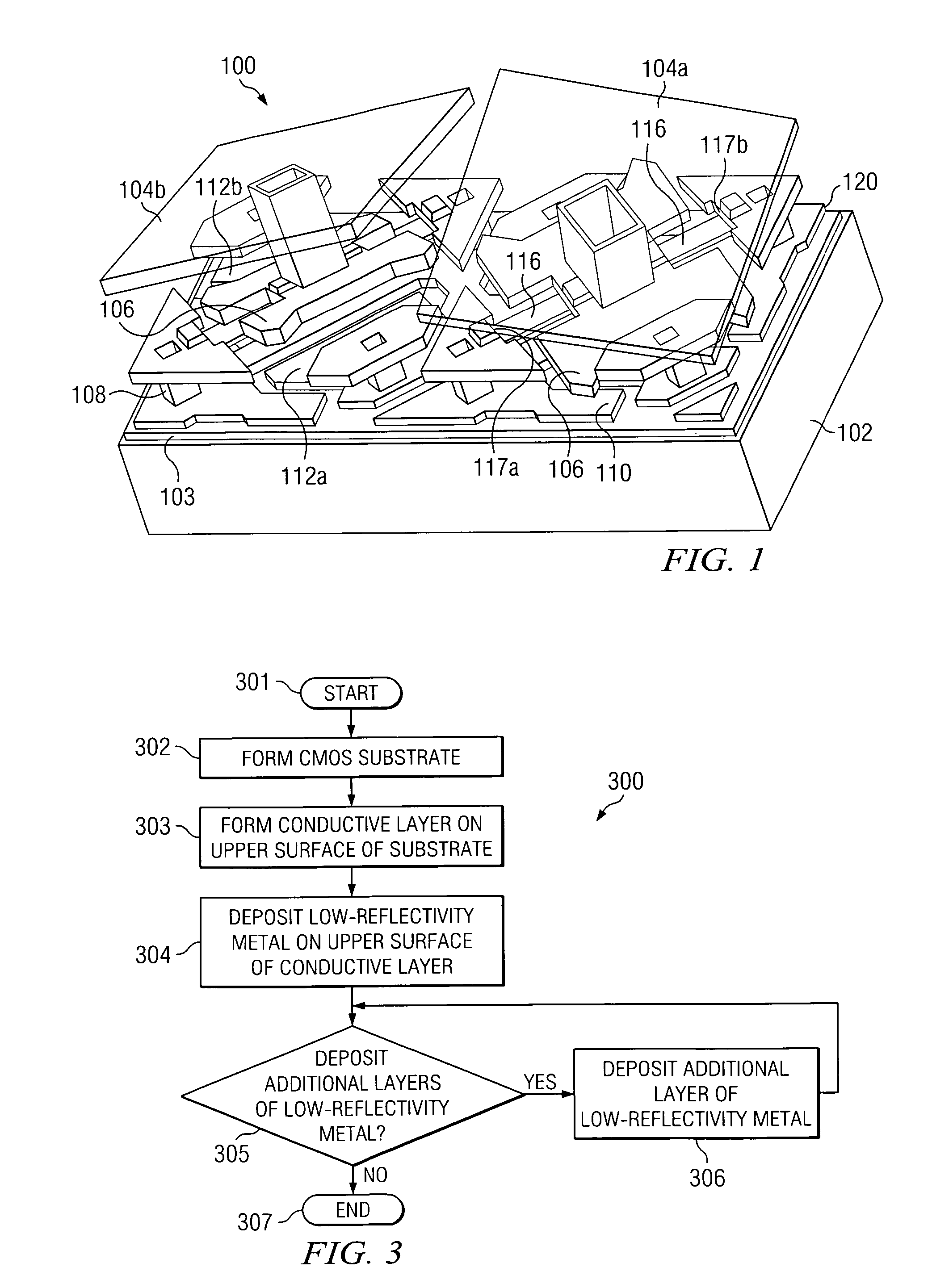
[0014]In accordance with a particular embodiment of the present invention, FIG. 1 illustrates a perspective view of a portion of a digital micro-mirror device (DMD) 100. DMD 100 employs a low-reflectivity coating over the conductive layer of the CMOS substrate of the DMD to reduce the reflectivity of the DMD superstructure and improve the contrast ratio of the DMD.

[0015]As shown in FIG. 1, DMD 100 comprises a micro electromechanical switching (MEMS) device that includes an array of hundreds of thousands of tilting micro-mirrors 104. In this example, each micro-mirror 104 is approximately 13.7 square microns in size and has an approximately one micron gap between adjacent micro-mirrors. In some examples, each micro-mirror can be less than thirteen square microns in size. In other examples, each micro-mirror can be approximately seventeen square microns in size. In addition, each micro-mirror 104 may tilt up to plus or minus ten degrees creating an active “on” state condition or an ac...


PUM

PropertyMeasurementUnit
wavelengthsaaaaaaaaaa
sizeaaaaaaaaaa
bias voltageaaaaaaaaaa

Abstract

According to one embodiment of the present invention, a digital micro-mirror device having improved contrast and a method for the same are provided. The digital micro-mirror device includes a plurality of current-carrying conductors on an upper surface of a substrate, each current-carrying conductor having an upper surface; a low-reflectivity metal disposed upon the upper surfaces of the current-carrying conductors; first and second micro-mirrors forming an aperture above the substrate; and wherein the low-reflectivity metal disposed upon on the upper surfaces of the current-carrying conductors reduces reflection of light received through the aperture by the current-carrying conductors.

Description

TECHNICAL FIELD[0001]This invention relates in general to optical processing devices and, more particularly, to a digital micro-mirror device having improved contrast and a method for the same.BACKGROUND[0002]Digital micro-mirror devices (DMD) are capable of being used in optical communication and / or projection display systems. DMDs involve an array of micro-mirrors that selectively communicate at least a portion of an optical signal or light beam by pivoting between active “on” and “off” states. To permit the micro-mirrors to pivot, each micro-mirror is attached to a hinge that is mounted on one or more support posts coupled to a CMOS substrate. Beneath the micro-mirrors and support posts the CMOS substrate used to control the movement of the micro-mirrors of the DMD. Unfortunately, when the micro-mirrors are in the “off” state, this CMOS substrate, which is optically reflective, may be exposed. As light passes between the micro-mirrors of the DMD, it may then be reflected by the s...

Claims


Application Information

Patent Timeline
Patent Type & Authority Patents(United States)
IPC IPC(8): G02F1/00
CPCG02B26/0841G02B5/22
Inventor DUNCAN, WALTER M.
Owner TEXAS INSTR INC
Why Eureka
Try Eureka