Slice image and/or dimensional image creating method

a dimensional image and cutting image technology, applied in the field of cutting image and/or dimensional image creation, can solve the problems of requiring time and effort for a calibration, inability to and large time and effort required for the calibration, so as to facilitate the processing of calibration and ensure the accuracy of the image. , the effect of preventing the generation of artifacts

Active Publication Date: 2007-03-06
SHIMADZU CORP
View PDF4 Cites 35 Cited by
  • Summary
  • Abstract
  • Description
  • Claims
  • Application Information

AI Technical Summary

Benefits of technology

[0008]This invention has been made having the state of the art noted above, and its object is to realize a rigid calibration for preventing generation of artifacts, and to facilitate a processing for calibration for securing required images efficiently.

Problems solved by technology

With the conventional apparatus, however, a rigid calibration is impossible when the track of the irradiating device and planar detector is even slightly displaced from a precise circular track about the rotation sectional axis.
With a small scan range of 40 degrees, for example, a wide range scan must be performed, resulting in a drawback of requiring time and effort for a calibration.
A great trouble must be taken until required images are secured.

Method used


Image

  • Slice image and/or dimensional image creating method
  • Slice image and/or dimensional image creating method
  • Slice image and/or dimensional image creating method

Examples


Embodiment Construction

[0044]A preferred embodiment of this invention will be described in detail hereinafter with reference to the drawings.

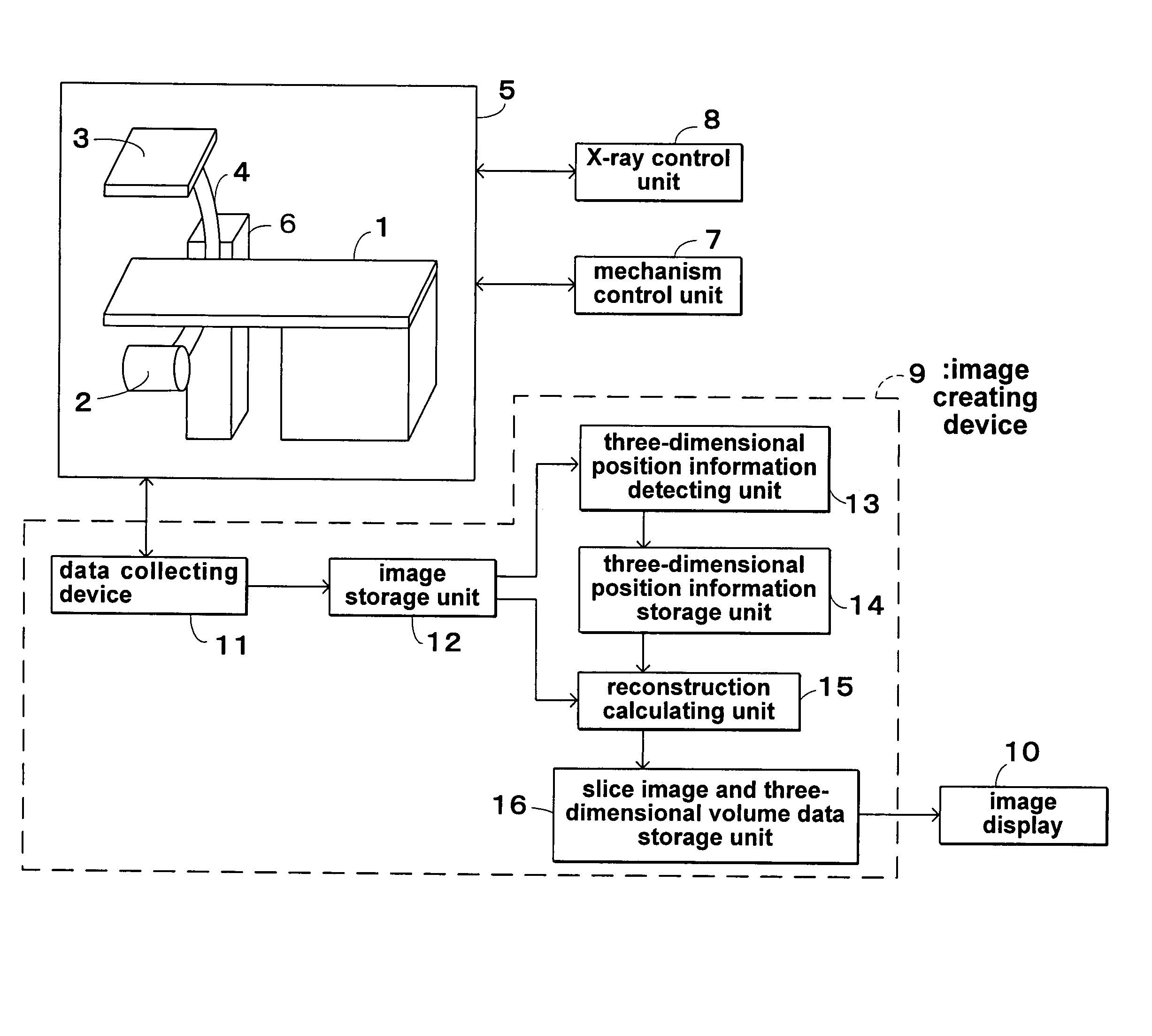
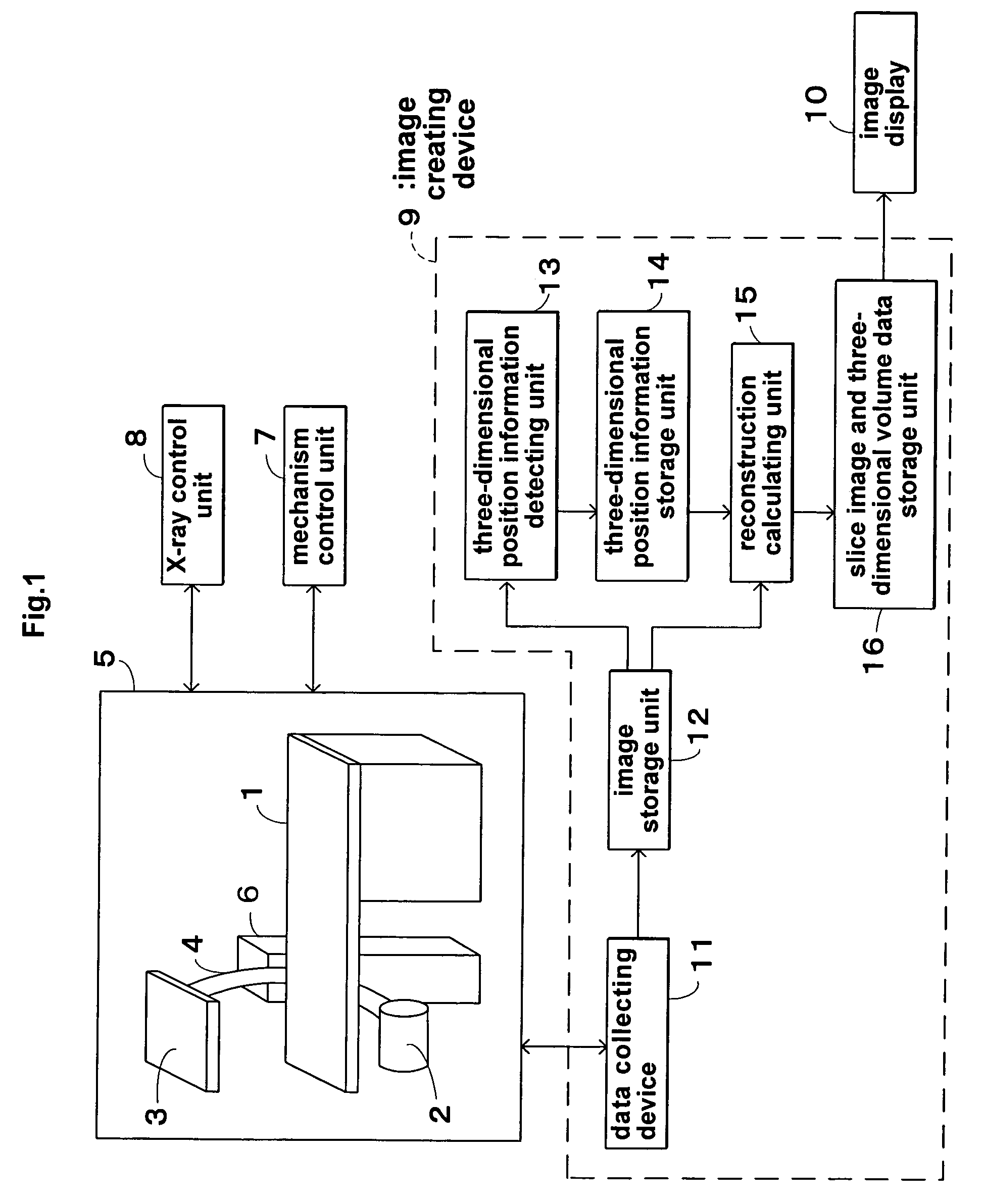
[0045]FIG. 1 is a block diagram showing a radiographic apparatus according to this invention. The apparatus includes a top board 1 for supporting a patient or object under examination, and an X-ray tube 2 and an area detector 3 held by a C-shaped arm 4 to be opposed to each other across the top board 1. The X-ray tube 2 acts as an irradiating device for emitting X rays in a diverging form to the patient. The area detector 3 acts as a planar detecting device having a plurality of pixels arranged in an array for detecting X rays transmitted through the patient. These components constitute an image pickup unit 5 of the apparatus.

[0046]The C-shaped arm 4 is connected to an actuator 6 acting as a moving device to be rotatable about a horizontal axis extending longitudinally of the top board 1 and about a horizontal axis extending perpendicular to the first-mentioned horiz...


PUM


Abstract

Projection images of a calibration phantom are picked up and stored. Three-dimensional position information on an X-ray tube and an area detector is obtained from the projection images and three-dimensional arrangement information on markers inside the calibration phantom. Three-dimensional position information is obtained for all projection images, and stored in a three-dimensional position information storage unit. Projection images of an object under examination are picked up by following the same tracks and the same sequence as when radiographing the calibration phantom. Radiographic data of the projection images is read. A reconstructing calculation is carried out for the object based on the three-dimensional position information on the X-ray tube and area detector relative to the calibration phantom, to create slice images or three-dimensional volume data of a selected site of the object.

Description

BACKGROUND OF THE INVENTION[0001](1) Field of the Invention[0002]This invention relates to a radiographic apparatus such as a fluoroscopic table, C-arm apparatus, X-ray CT apparatus, general photographic apparatus or the like for use in the medical or industrial field. The apparatus includes an irradiating device for emitting a penetrating electromagnetic wave in a diverging form to a patient or object under examination, a planar detecting device opposed to the irradiating device across the patient or object and having a plurality of pixels arranged in an array for detecting the electromagnetic wave transmitted through the patient or object, a moving device for moving the irradiating device and planar detecting device as synchronized with each other, and an image creating device for acquiring projection images of the patient or object irradiated by the electromagnetic wave emitted from varied directions by the action of the moving device, and performing a reconstructing calculation ...

Claims


Application Information

Patent Timeline
Patent Type & Authority Patents(United States)
IPC IPC(8): G01D18/00A61B6/00
CPCA61B6/466A61B6/583A61B6/4092A61B6/00
Inventor MORITA, HISANORIOIKAWA, SHIRO
Owner SHIMADZU CORP
Why Eureka
Try Eureka