Roller construction for detritus removal

a technology of detritus removal and construction, which is applied in the direction of shafts and bearings, household cleaners, artistic surface treatment, etc., can solve the problems of inability to conform to non-planar surfaces, inability to effectively remove detritus from the surface, and inability to retain electrostatic charge of paper backing used for stripping, etc., to achieve enhanced detritus removal, effective removal of detritus from the surface, and better carrier

Inactive Publication Date: 2007-03-06
BUTLER HOME PRODUCTS LLC
View PDF21 Cites 9 Cited by
  • Summary
  • Abstract
  • Description
  • Claims
  • Application Information

AI Technical Summary

Benefits of technology

[0011]Unlike the previously known adhesive rollers, however, the backing layer for the adhesive roller of the present invention is made of a material which retains or creates an electrostatic charge, such as foam and preferably a closed-cell foam or a non-woven static retaining material, such as polyethylene, proproplyene or polyolefan. A backing of a low-density or bi-density polyethylene film would help add strength to each layer and minimize shredding. The use of foam and / or non-woven material for the backing strip provides several advantages.
[0012]First, the backing layer is compressible and flexible unlike the previously known adhesive rollers so that the adhesive roller can conform to non-planar surfaces, such as a tile floor. In doing so, the compressibility and flexibility of the backing layer ensures that the adhesive roller maintains contact with the entire surface of non-planar surfaces thus effectively removing detritus from that surface.
[0013]A still further advantage of these backing layers is that the backing layer provides a better carrier for certain coatings and infusion layers. These coatings and infusion layers include, for example, antimicrobial coatings and fragrance coatings.
[0015]In a different embodiment, the backing layer is coated or impregnated with an antistatic agent that minimizes or eliminates static from the surface being cleaned.
[0016]Preferably, perforations or a cut are formed at predetermined intervals along the strip so that the interval between adjacent perforations corresponds substantially to one full revolution of the strip around the roll. Thus, when the adhesive on the outermost layer becomes depleted, a single layer is easily removed from the roll thus exposing fresh adhesive. Furthermore, the use of the foam or non-woven material as the backing layer also minimizes the likelihood of tearing of the strip during removal of the outermost layer except along the desired perforation line.
[0017]In a still further embodiment of the invention, the detritus removal roller comprises an elongated strip of non-woven electrostatic charge retaining material wound into a cylindrical roll but without an adhesive coating on the outwardly facing surface of the roll. In this embodiment the detritus removal is achieved by the electrostatic attraction between the roll and the detritus rather than by adhesive retention. Perforations, or a cut line, are preferably provided at spaced intervals along the strip corresponding substantially to one revolution of the roll to facilitate the removal of individual layers of the roll.

Problems solved by technology

One disadvantage of these previously known adhesive rollers is that the roller itself is relatively rigid in construction.
As such, the roller is unable to conform to non-planar surfaces, such as a tile floor.
A still further disadvantage of these previously known adhesive rollers is that the paper backing used for the strip does not retain an electrostatic charge.
A still further disadvantage of these previously known adhesive rollers is that the paper backing used with these adhesive rollers does not form an adequate carrier for certain coatings.

Method used


Image

  • Roller construction for detritus removal
  • Roller construction for detritus removal
  • Roller construction for detritus removal

Examples


Embodiment Construction

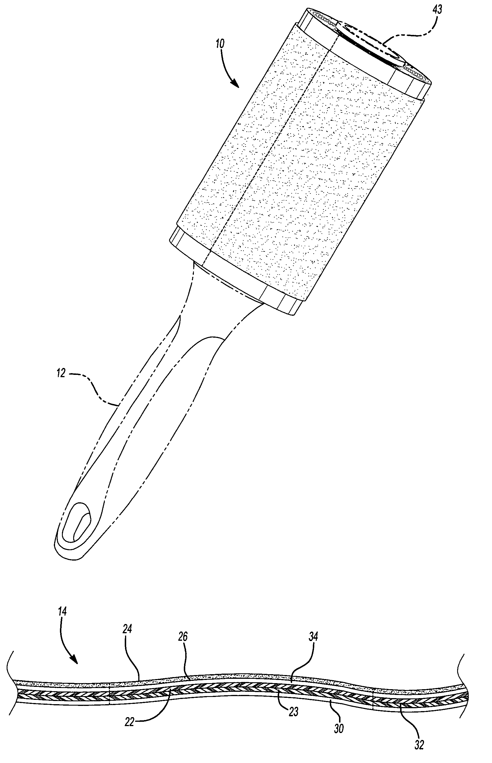
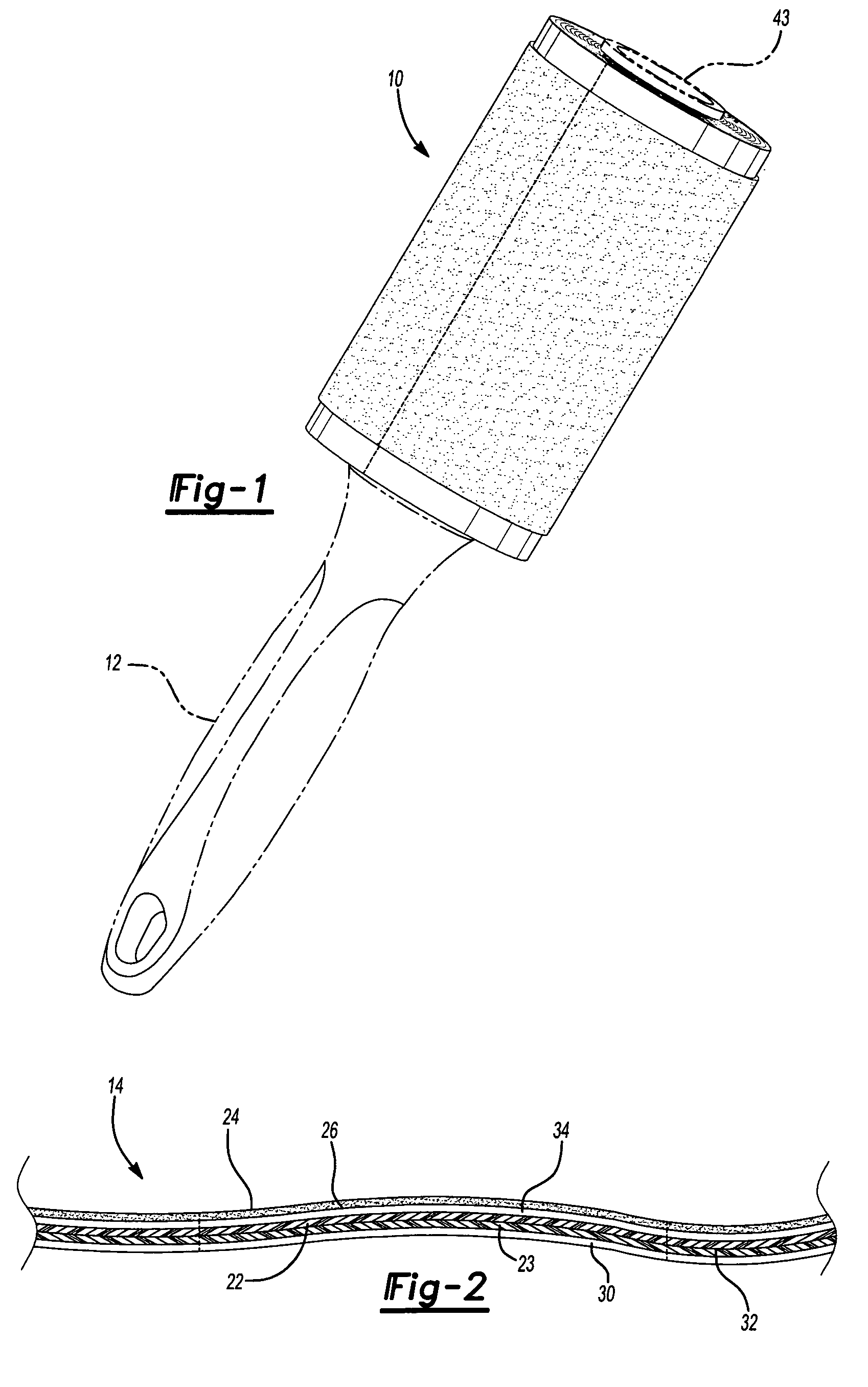
[0024]With reference first to FIG. 1, a preferred embodiment of the detritus removal roller construction 9 of the present invention is shown and comprises an adhesive roller construction 10 mounted to a handle 12 so that the roller construction 10 rotates relative to the handle 12. Furthermore, as illustrated in FIG. 1, the adhesive roller construction 10 is illustrated as a lint roller. No undue limitations, however, should be drawn therefrom since the adhesive roller construction 10 can also be used for many other applications, such as floor sweepers and the like.

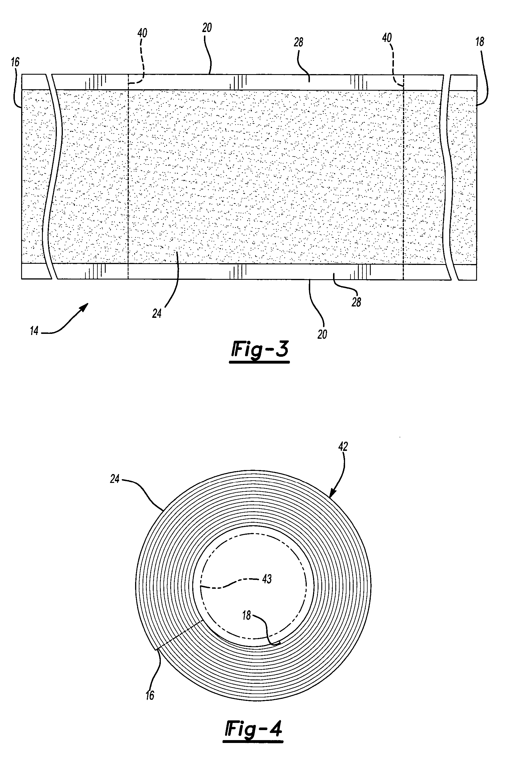
[0025]With reference now to FIGS. 2 and 3, the adhesive roller construction 10 comprises an elongated strip 14 having a first end 16, a second end 18 and two spaced apart sides 20. The elongated strip 14, furthermore, includes both a backing layer 22 and an adhesive layer 24 overlying at least a portion of one side 26 of the backing layer 22. However, as best shown in FIG. 3, the adhesive layer 24 is preferably spaced inw...


PUM


Abstract

A detritus removal roller construction particularly suited for a lint roller is disclosed having an elongated strip with a backing layer and an adhesive layer overlying one side of the backing layer. The strip has a first end, a second end and two spaced apart sides and is wound from its first end to its second end into a tubular cylindrical roll. The backing layer is made of a compressible material which retains and / or creates an electrostatic charge in use.

Description

BACKGROUND OF THE INVENTION[0001]I. Field of the Invention[0002]The present invention relates generally to rollers used for detritus removal.[0003]II. Description of Related Art[0004]Lint rollers have been long known and widely used for removing foreign particles, such as pet hair, lint and other detritus from flooring, clothing and the like. These previously known lint rollers typically comprise a handle having a tubular and cylindrical tape roll rotatably mounted to the handle.[0005]Many of the previously known adhesive rollers for lint removal comprise a continuous strip having a paper backing layer with adhesive provided along one side of the backing. The strip is wound into a cylindrical roll, typically around a core, so that the adhesive faces outwardly. As the adhesive becomes depleted from use, a portion of the strip is torn from the roll to expose fresh adhesive on the next inner layer of the strip. This process continues until the entire roll has been depleted, at which ti...

Claims


Application Information

Patent Timeline
Patent Type & Authority Patents(United States)
IPC IPC(8): B25F5/02B05C1/08A47LA47L25/00F16C13/00
CPCA47L25/005A47L13/40
Inventor MCKAY, JR., NICHOLAS D.WILLIAMSON, PETER JOHN
Owner BUTLER HOME PRODUCTS LLC
Why Eureka
Try Eureka