Method and apparatus for correcting tilt of light beam to optical recording medium

a technology of light beam and optical recording medium, which is applied in the direction of digital signal error detection/correction, instruments, recording signal processing, etc., can solve the problems of unable to mount such a tilt sensor on the slim disk drive, pick-up device equipped with a larger sensor in the size, etc., and achieve the effect of avoiding tilt correcting apparatus

Inactive Publication Date: 2007-03-06
PIONEER CORP
View PDF11 Cites 9 Cited by
  • Summary
  • Abstract
  • Description
  • Claims
  • Application Information

AI Technical Summary

Benefits of technology

[0007]The present invention has been made with due consideration to the foregoing drawbacks, and an object of the present invention is to provide a tilt correcting apparatus capable of correcting a tilt of an optical recording medium without using the dedicated tilt sensor, whereby the tilt correcting apparatus is avoided from becoming larger in the physical size.

Problems solved by technology

One problem arising when using such a dedicated tilt sensor is that the sensor itself is larger in the physical size, thus making a pickup device equipped with the sensor larger in the size.
Hence, a slim disk drive, which is often mounted in notebook-size personal computers, has faced this problem.
That is, it is impossible for the slim disk drive to have such a tilt sensor mounted therein.

Method used


Image

  • Method and apparatus for correcting tilt of light beam to optical recording medium
  • Method and apparatus for correcting tilt of light beam to optical recording medium
  • Method and apparatus for correcting tilt of light beam to optical recording medium

Examples


example

[0045]A preferred example of the above embodiment will now be explained.

[0046](Information Recording / Reproducing System)

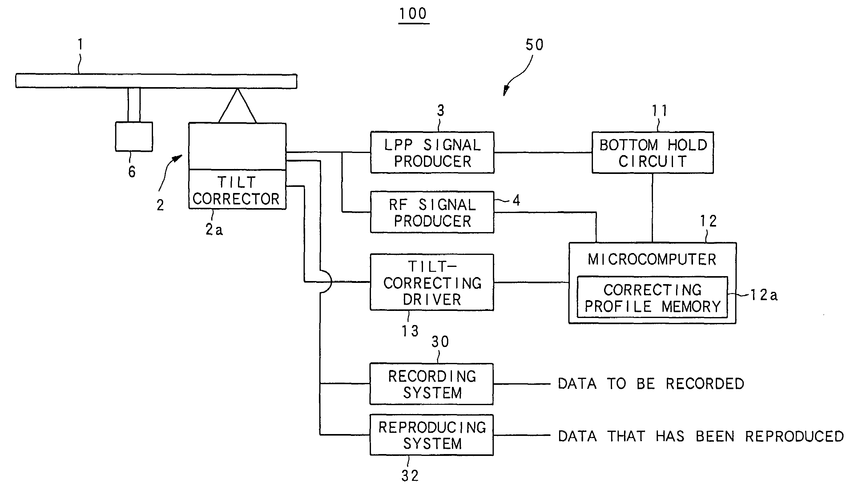
[0047]FIG. 4 is a block diagram outlining the configuration of an information recording / reproducing system according to an example realized based on the foregoing embodiment.

[0048]As shown in FIG. 4, the disk 1 is subjected to the control for CLV (Constant Linear Velocity), which is carried out by the spindle motor 6, so that the disk 1 is rotated at a constant velocity. In the configuration of FIG. 4, there is provided an information recording / reproducing system 100, which is provided with, from a roughly-sectioned point of view, a recording system 30 configured to record recording data onto the disk 1, a reproducing system 32 configured to reproduce data recorded on the disk 1, and a tilt correcting apparatus 50 configured to correct the radial tilt to the disk 1. Of these components, both of the recording and reproducing systems 30 and 32 can be configured with ...


PUM

PropertyMeasurementUnit
angular velocityaaaaaaaaaa
sizeaaaaaaaaaa
physical sizeaaaaaaaaaa

Abstract

A tilt of a light beam to be radiated onto an information recording disk is corrected without using a dedicated tilt sensor. The correction is performed based on the characteristic that an offset amount between a tilt amount maximizing an RF signal amplitude and a further tilt amount maximizing an LPP signal amplitude is constant and independent of positions on the same disk. A pre-pit signal indicative of an existence / nonexistence of a pre-pit formed on the disk is produced from returned light of the light beam, while an RF signal is produced from bits of information recorded on the disk on the basis of the returned light. An optimum tilt-correcting amount is decided by making use of a relationship between the pre-pit signal and the RF signal at a particular tilt amount. The tilt amount is corrected using the optimum tilt-correcting amount.

Description

BACKGROUND OF THE INVENTION[0001]1. Field of the Invention[0002]The present invention relates to a method and apparatus for correcting the tilt of a light beam to optical recording mediums such as optical disks.[0003]2. Description of the Related Art[0004]In general, in recording and reproducing bits of information onto and from an optical disk, a tilt correcting technique has been adopted. The tilt correction is to correct a tilt of an optical beam (also known as “radial tilt”) to the information recording surface of an optical disk. Thus, when the tilt is corrected exactly, the optical beam should be radiated at right angles onto the information recording surface of an optical disk.[0005]A conventional detection of the radial tilt has been carried out using a dedicated tilt sensor. Such a dedicated tilt sensor is configured to have an optical source to radiate a light beam dedicated for the radial tilt detection toward the information recording surface of an optical disk and a det...

Claims


Application Information

Patent Timeline
Patent Type & Authority Patents(United States)
IPC IPC(8): G11B20/20G11B7/005G11B7/095
CPCG11B7/0956G11B7/0053
Inventor KATO, MASAHIROYONE, TATSUHIROYOSHIDA, SHIGERUISHIHARA, KANJI
Owner PIONEER CORP
Why Eureka
Try Eureka