Optical time delay system

Active Publication Date: 2007-03-06
WAVEFRONT RES
View PDF7 Cites 4 Cited by
  • Summary
  • Abstract
  • Description
  • Claims
  • Application Information

AI Technical Summary

Benefits of technology

[0007]In one embodiment of the present invention two or more White Cells are used to each multiply image across the face of one of a pair of symmetric pixellated switchable elements, pixellated switchable gratings in one embodiment—one pixellated switchable grating in each White Cell. In one embodiment the pi

Problems solved by technology

However, existing art is limited in application to phased array beamforming due to lifetime issues.
For systems utilizing MEMS devices, pointing stability of the mechanically deflected mirrors is an issue.

Method used


Image

  • Optical time delay system
  • Optical time delay system
  • Optical time delay system

Examples


Embodiment Construction

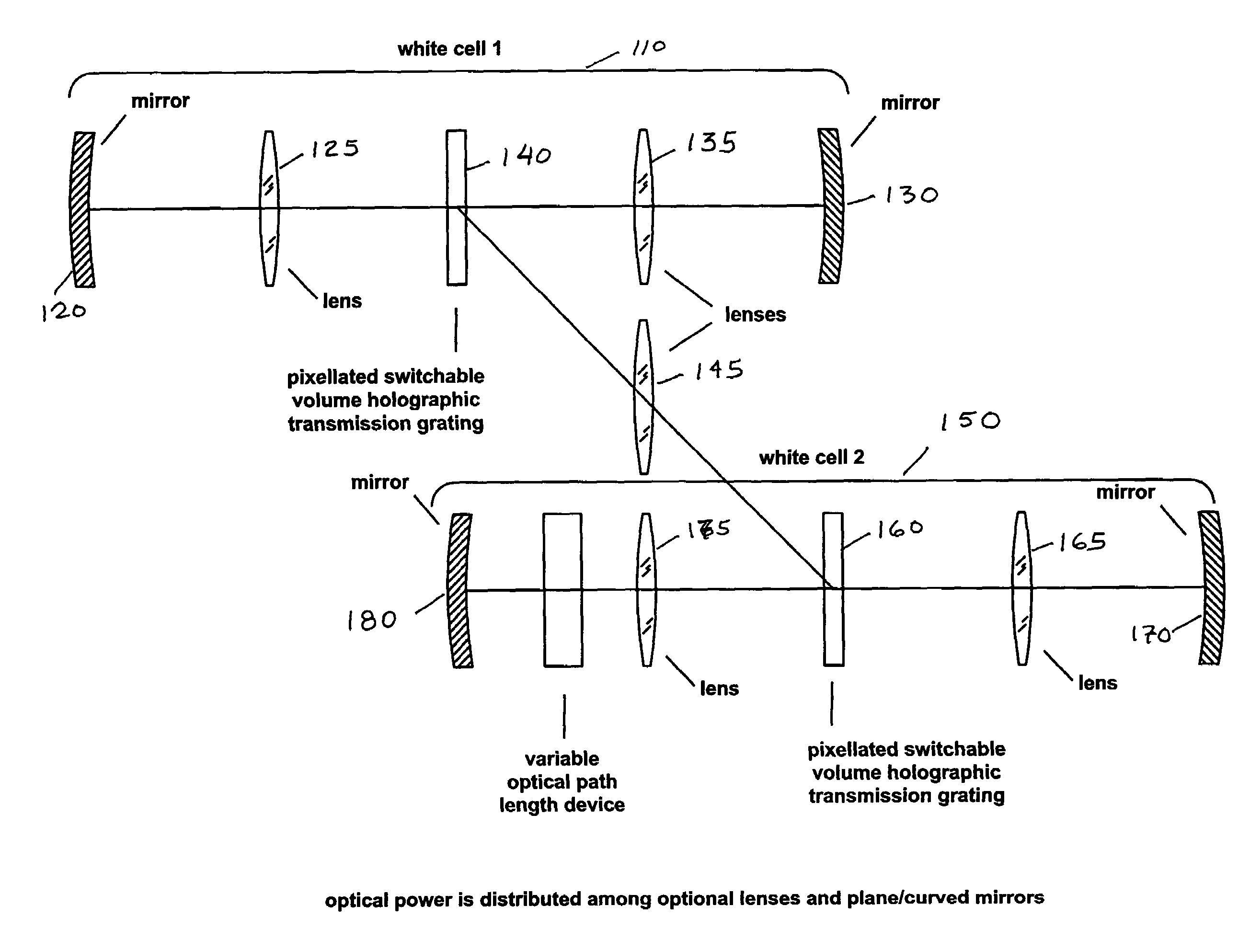
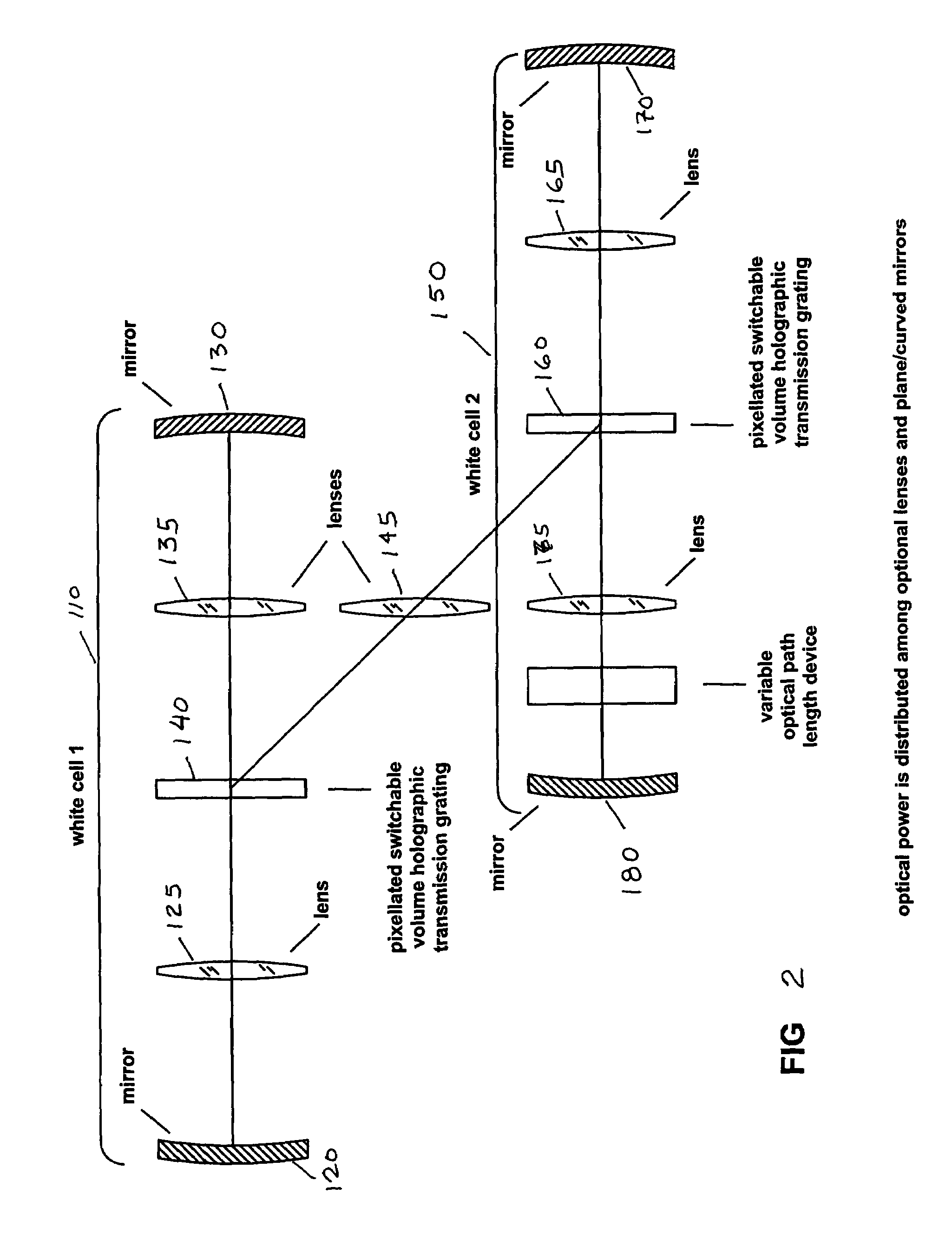
[0013]Optical systems utilizing pixellated switchable elements to provide interaction between at least two White Cells are disclosed hereinbelow.

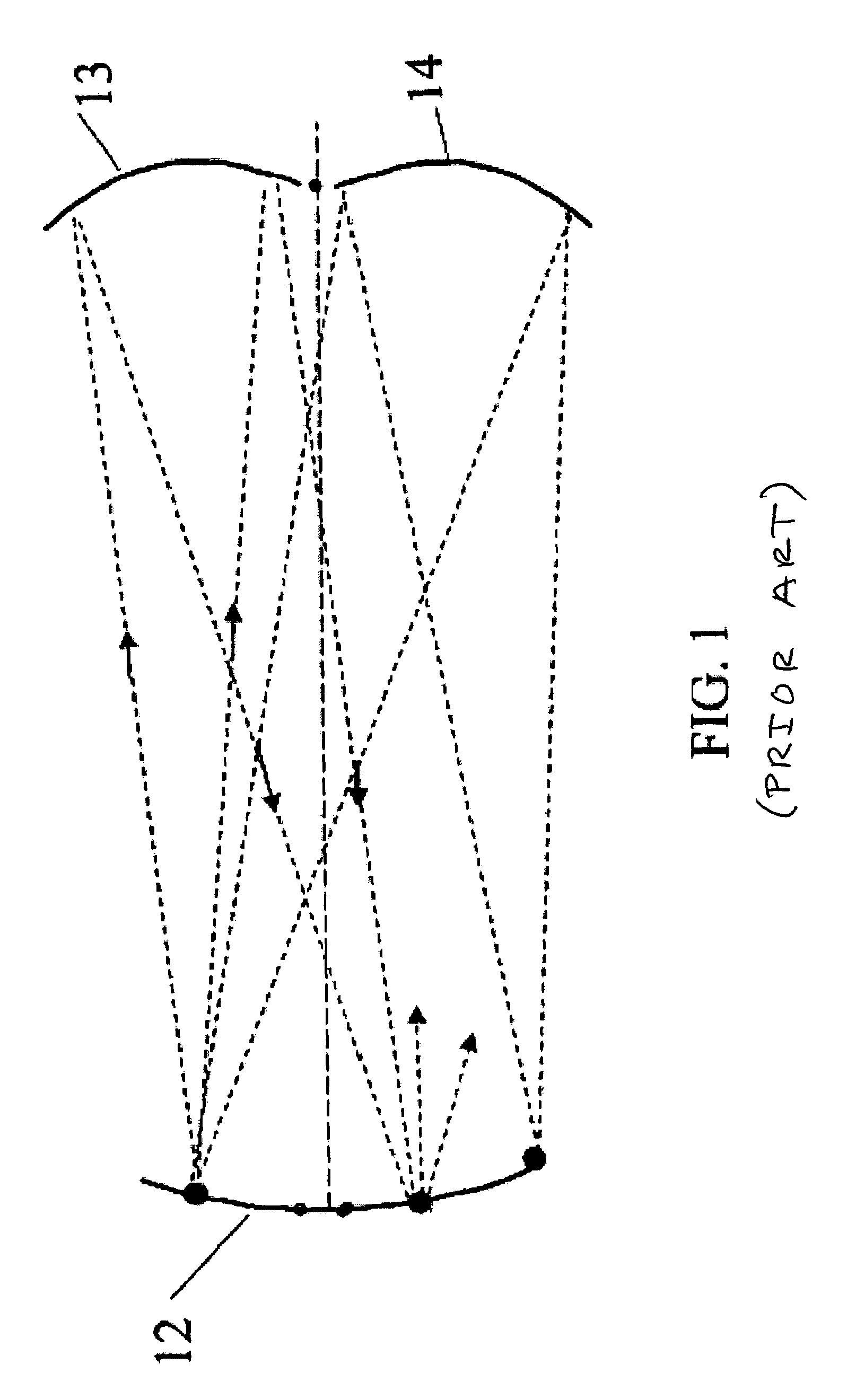
[0014]The present invention is based on the conventional White cell, shown in FIG. 1. A diagram of the path of a light beam passing through a conventional White cell is also shown in FIG. 1. The cell comprises three identical spherical mirrors 12, 13, 14, all of the same radius of curvature. Electromagnetic radiation (hereinafter also referred to as light) from the second mirror is imaged onto the third mirror, and vice versa. The beam may traverse the cell a predetermined number of times, depending on the locations of the centers of curvature of the second and third mirrors.

[0015]In one embodiment of the present invention, shown in FIGS. 2 and 3, two White Cells are used to each multiply image across the face of one of a pair of symmetric pixellated switchable elements—symmetric pixellated switchable gratings in one embodiment, one pixella...


PUM


Abstract

Optical systems utilizing pixellated switchable elements to provide interaction between at least two White Cells.

Description

CROSS REFERENCE TO RELATED APPLICATIONS[0001]This application claims priority of U.S. Provisional Application 60 / 519,738 filed on Nov. 12, 2003, which is incorporated by reference herein.BACKGROUND OF THE INVENTION[0002]This invention relates to an improved optical time delay system based on switchable diffraction gratings and a White Cell geometry. The use of the switchable diffraction gratings in the form of switchable transmission gratings and switchable volume holographic mirrors adds a reliable electro-optic switch technology with low insertion loss, low crosstalk, and high reliability to relatively compact White Cell based time delay systems.[0003]White Cell geometries have been previously used for time delay systems. In the original White cell, light bounces back and forth repeatedly between three spherical mirrors, all identical, and is focused to a new spot on every bounce. A number of proposed systems use a White Cell multi-pass approach in conjunction with spatial light m...

Claims


Application Information

Patent Timeline
IPC IPC(8): G02B6/35G02B5/32
CPCG02B17/004
Inventor STONE, THOMAS W.MITCHELL, THOMAS A.
Owner WAVEFRONT RES
Why Eureka
Try Eureka