Method and apparatus for testing optical networks

a technology of optical networks and optical networks, applied in the direction of transmission monitoring/testing/fault-measurement systems, transmission monitoring/testing/measurement systems, structural/machine measurement, etc., can solve the problems of large instrument cost and complicated routine field application,

a technology of optical networks and optical networks, applied in the direction of transmission monitoring/testing/fault-measurement systems, transmission monitoring/testing/measurement systems, structural/machine measurement, etc., can solve the problems of large instrument cost and complicated routine field application,

US7187861B2Inactive Publication Date: 2007-03-06EXFO ELECTRO OPTICAL ENG

Image

  • Method and apparatus for testing optical networks
  • Method and apparatus for testing optical networks
  • Method and apparatus for testing optical networks

Examples


Embodiment Construction

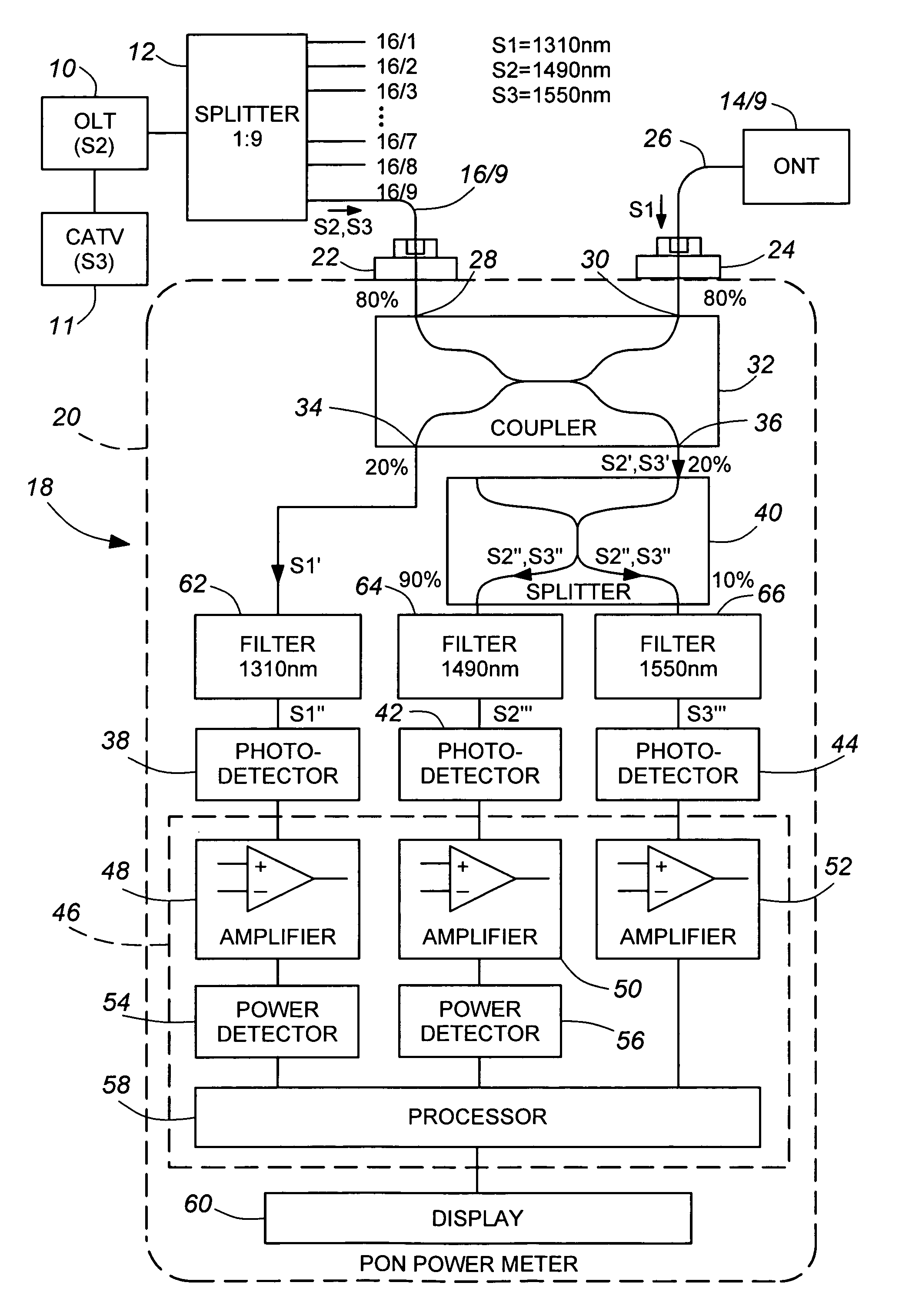
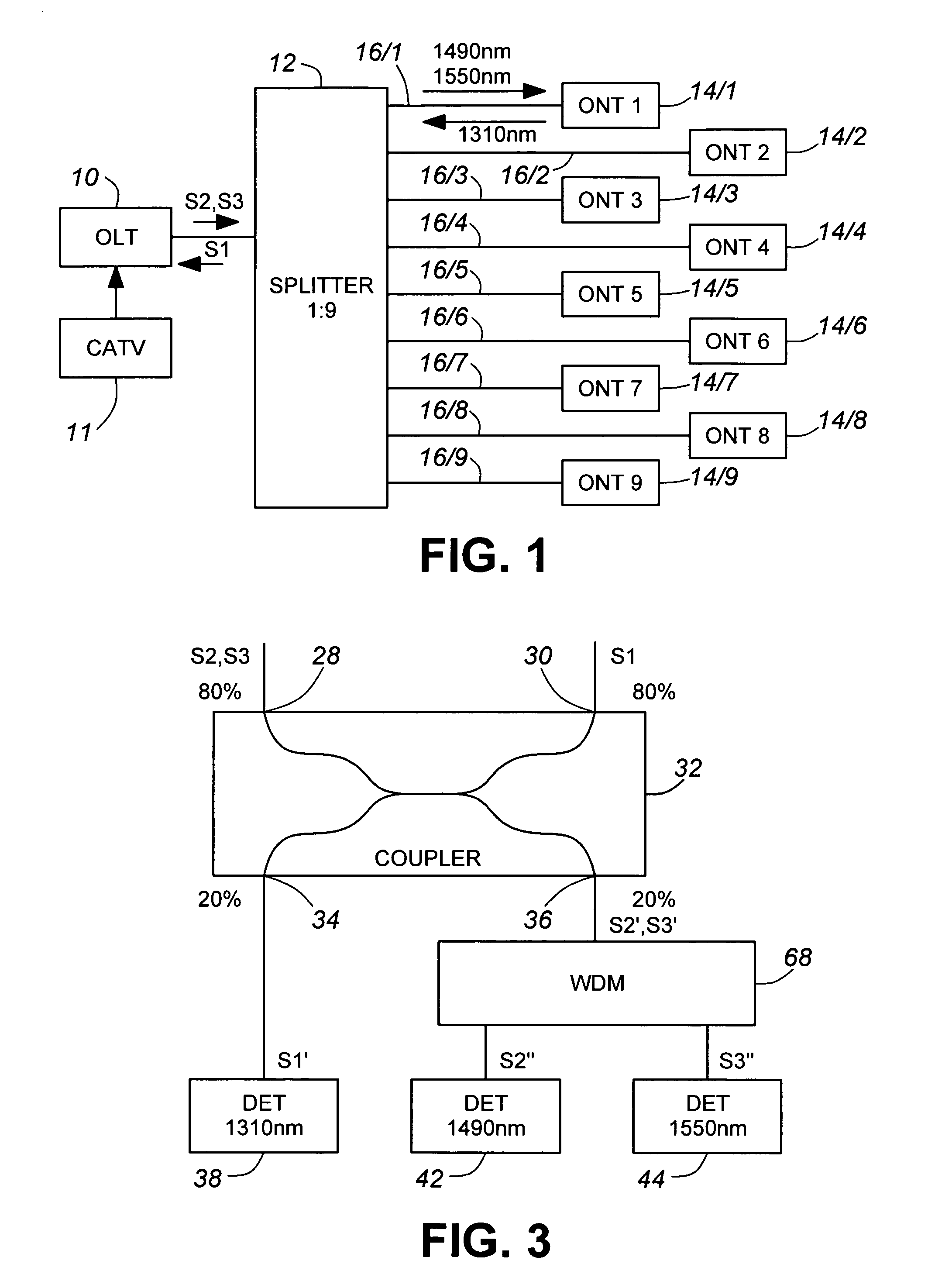
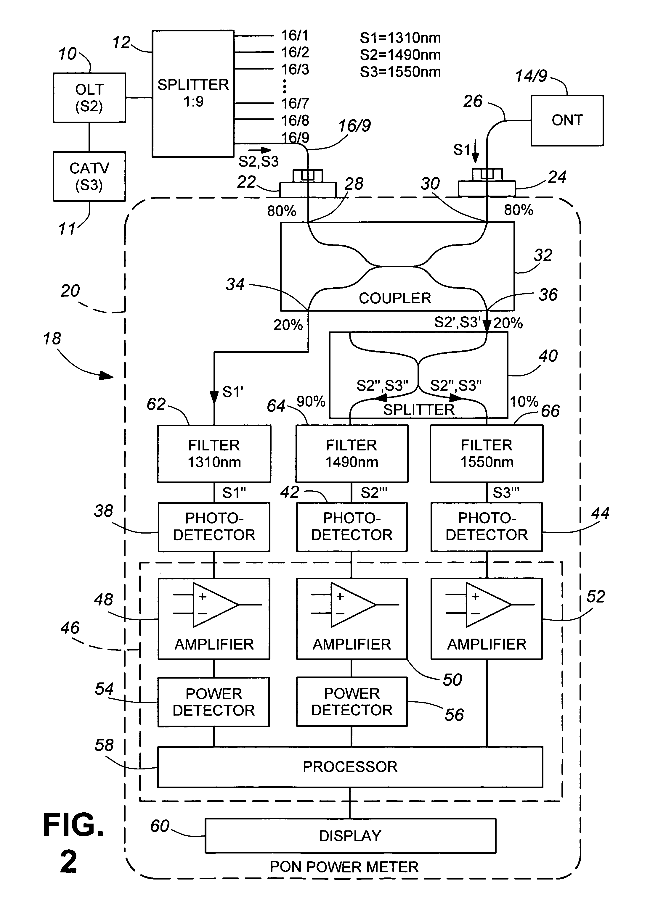
[0035]A portion of a passive optical network shown in FIG. 1 comprises a first element in the form of a central office optical line terminal (OLT) 10 coupled by a 1:9 splitter 12 to a plurality of other elements in the form of optical network terminals (ONT) 14 / 1 to 14 / 9, each coupled to a respective one of the nine ports of the splitter 12 by one of a corresponding plurality of optical waveguides 16 / 1 to 16 / 9. (It should be noted that, although nine terminals and a nine-port splitter are shown for convenience of illustration, there could be more or fewer in practice.) The terminals use asynchronous transfer mode (ATM) or similar protocol to encode the downstream (OLT to ONTs) and upstream (ONTs to OLT) digital data signals. OLT 10 broadcasts to the ONTs 14 / 1 to 14 / 9 downstream data signals (S2) at a wavelength of 1490-nm and downstream cable television (CATV) signals (S3) at a wavelength of 1550-nm and, in known manner, encodes the 1490-nm signals for synchronization purposes, the ...


PUM

PropertyMeasurementUnit
wavelengthaaaaaaaaaa
wavelengthsaaaaaaaaaa

Abstract

An instrument for measuring bidirectional optical signals propagating in an optical transmission path between elements one of which will not transmit if continuity of the transmission path is not maintained, for example a branch path between a central offices optical line terminal (OLT) and an end-user's optical network terminal (ONT), comprises first and second connector receptacles for connecting the instrument into the path, a 2×2 coupler (32) having first and second ports (28, 30) connected to the first and second connectors (22, 24), respectively, for completing the optical transmission path, a third port (36) for, outputting a portion of each optical signal received via the first port (28) and a fourth port (34) for outputting a portion of each optical signal received via the second port (30) Detectors (38, 42, 44) coupled to the third and fourth ports convert the optical signal portions into corresponding electrical signals, which are processed to provide the desired measurements. The measurement results may be displayed by a suitable display unit (60) Where the ÖLT transmits signals at two different wavelengths, the instrument may separate parts of the corresponding optical signal portion according to wavelength and process them separately.

Description

CROSS-REFERENCE TO RELATED APPLICATION[0001]This application claims priority from U.S. Provisional patent application No. 60 / 511,105 filed Oct. 15, 2003, the entire contents of which are incorporated herein by reference.FIELD OF THE INVENTION[0002]The invention relates to a method and apparatus for testing optical networks and is especially, but not exclusively, applicable to a method and apparatus for measuring signals in optical transmission lines of passive optical networks.BACKGROUND ART[0003]As the cost of optical fiber and associated components decreases, new telecommunications network deployments increasingly use optical fiber from the edge of a core network to a location at or very close to the end user. Such so-called FTITX (Fiber-to-the-X; where X is the home, the office, the building the curb, etc.) installations are usually based on a passive optical network (PON) architecture, where a terminal at the core-network edge (Optical Line Terminal—OLT) broadcasts signals downs...

Claims


Application Information

Patent Timeline
06 Mar 2007
Publication
US7187861B2
IPC
H04B10/08; G01N21/00; H04B17/00; H04B10/02
CPC
H04B10/079; H04B10/07953; H04B3/46; H04B10/0795; H04B10/07955; H04Q11/0067; H04B10/0793; H04Q2011/0083
Inventors
RUCHET, BERNARD