Appliance diagnostic display apparatus and network incorporating same

a technology of diagnostic display and display apparatus, which is applied in the direction of computer control, electric signalling details, temperatue control, etc., can solve the problems of large reduction in service time required to diagnose, inability to display diagnostic information by the user, and inability to meet the needs of consumers

Inactive Publication Date: 2007-03-06
INVENSYS SYST INC
View PDF15 Cites 178 Cited by
  • Summary
  • Abstract
  • Description
  • Claims
  • Application Information

AI Technical Summary

Benefits of technology

[0007]In an embodiment of the present invention, an advanced thermostat that includes a user interface and wireless or wired network communications capability to enable control and diagnostic communications between the thermostat and the various consumer appliances in the home. The thermostat user interface allows the homeowner or service technician to view diagnostic information for the appliances as well as execute system tests. The thermostat could then display the results of any such system tests. In this way, the system of the present invention leverages the graphical user interface provided by the thermostat to enable advanced diagnostics and system tests of appliance controls.

Problems solved by technology

Indeed, consumers have come to demand increased sophistication in the cycles provided by their appliances.
This functionality greatly reduces the service time required to diagnose a problem with an appliance by a service technician when a problem with the appliance occurs.
Unfortunately, most consumer appliances do not include an easy means to display this diagnostic information, including product failures, to a homeowner or a service technician.
Adding such a user interface display to many of these appliances is not cost effective.
Unfortunately, most consumers do not have the equipment necessary to download this diagnostic information from the appliance, and therefore must resort to prior troubleshooting methods if they wish to maintain their appliance themselves, or must call a service technician.

Method used


Image

  • Appliance diagnostic display apparatus and network incorporating same
  • Appliance diagnostic display apparatus and network incorporating same
  • Appliance diagnostic display apparatus and network incorporating same

Examples


Embodiment Construction

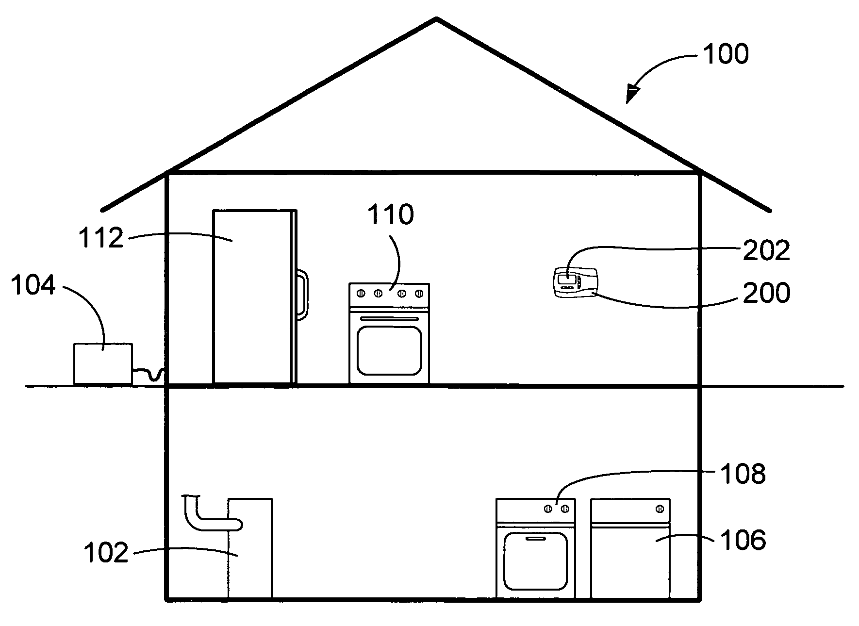
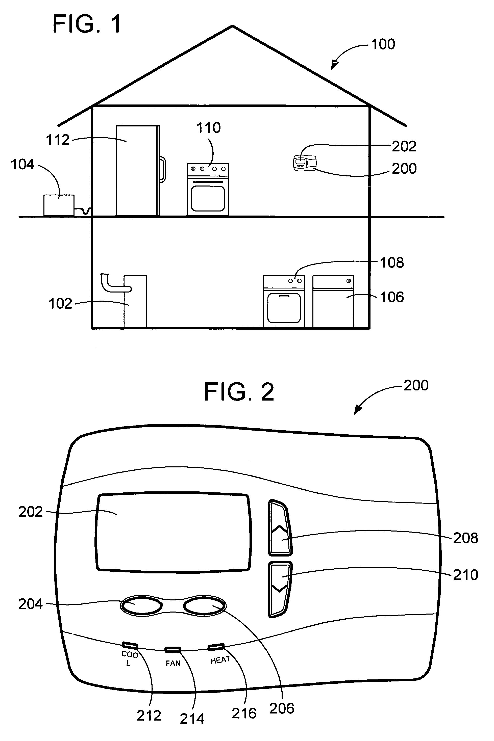
[0013]FIG. 1 illustrates a simplified home environment 100 into which the system of the present invention finds particular applicability. However, one skilled in the art will recognize that the system of the present invention is not limited to a home environment, but may also be installed in a commercial environment, etc. This typical home environment 100 includes an intelligent thermostat 200. As is typical, the thermostat 200 controls heating of the home environment 100 by the furnace 102, and possibly cooling of the home environment 100 by the air conditioning system 104. The interface to both the furnace 102 and the air conditioning system 104 is typically pre-wired in the home environment 100, although the communications control from the thermostat 200 to the furnace 102 and to the air conditioning system 104 may also be wireless as desired by providing receiver / transmitter circuitry in the furnace 102 and air conditioning system 104. Similar receiver / transmitter circuitry is a...


PUM


Abstract

An appliance diagnostic display and interface system providing a centralized user interface for appliance diagnostic information and control of system self-tests is provided. This centralized user interface is provided via an intelligent thermostat that includes an LCD display. The intelligent thermostat interfaces, via wireless or wired communications, with the appliances installed in the home. The intelligent thermostat then generates and displays various user interface screens that allow particular appliances to be selected. Separate appliance specific screens are then generated that allow the user to access the diagnostic information in system test functionality provided by the individual appliance. Soft function keys provided on the intelligent thermostat allow multi-functional access to the features of the invention depending on which screen is currently being displayed.

Description

CROSS-REFERENCE TO RELATED PATENT APPLICATIONS[0001]This patent application claims the benefit of U.S. Provisional Patent Application Ser. No. 60 / 535,287, filed Jan. 8, 2004, the teachings and disclosure of which are hereby incorporated in their entireties by reference thereto.FIELD OF THE INVENTION[0002]The present invention relates generally to diagnostic and self-test systems, and more particularly to appliance diagnostic and self-test systems for consumer appliances and the like.BACKGROUND OF THE INVENTION[0003]As consumer electronics continue to decrease in cost and increase in reliability and features provided, their use in many consumer products becomes more practical, and even desirable. One factor contributing to the acceptability of electronic controls in many consumer products, including consumer home appliances, is that the population as a whole are becoming more computer literate and used to electronic displays and push button controls. No longer are consumers turned of...

Claims


Application Information

Patent Timeline
Patent Type & Authority Patents(United States)
IPC IPC(8): G01M1/38G05B13/00G05B15/00G05B21/00G05D23/00G05B11/01F24F11/00G05B23/02G05D23/19
CPCF24F11/0086G05B23/0216G05D23/1902F24F11/30F24F11/52F24F11/38
Inventor CHAPMAN, JR., JOHN GILMANASHWORTH, NICHOLASBURT, ROBERTWALLAERT, TIMOTHY E.
Owner INVENSYS SYST INC
Why Eureka
Try Eureka