

Reciprocating engine and inlet system therefor
a reciprocating engine and working fluid technology, applied in the direction of lift valves, rotary slide valves, steam engine plants, etc., can solve the problems of poor efficiencies, reduced use of steam engines, and limited valve actuation technology, and achieve the effect of prolonging the life of reed valves and high expansion ratio
- Summary
- Abstract
- Description
- Claims
- Application Information
AI Technical Summary
Benefits of technology
Problems solved by technology
Method used
Image

Examples
Embodiment Construction
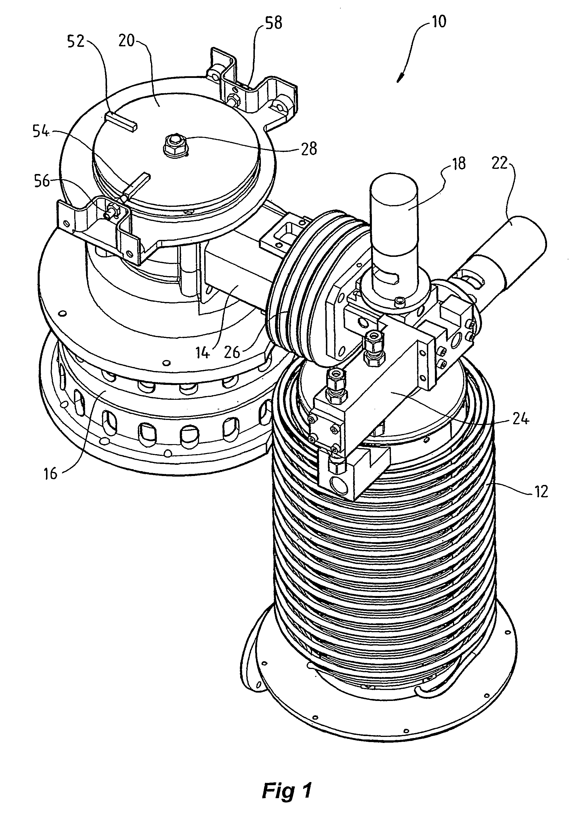
[0071]Illustrated in FIG. 1 is a reciprocating engine 10 that operates on the Rankine cycle and uses steam as its working fluid. The engine 10 is not illustrated with all of the components necessary for operation, as will be explained shortly.
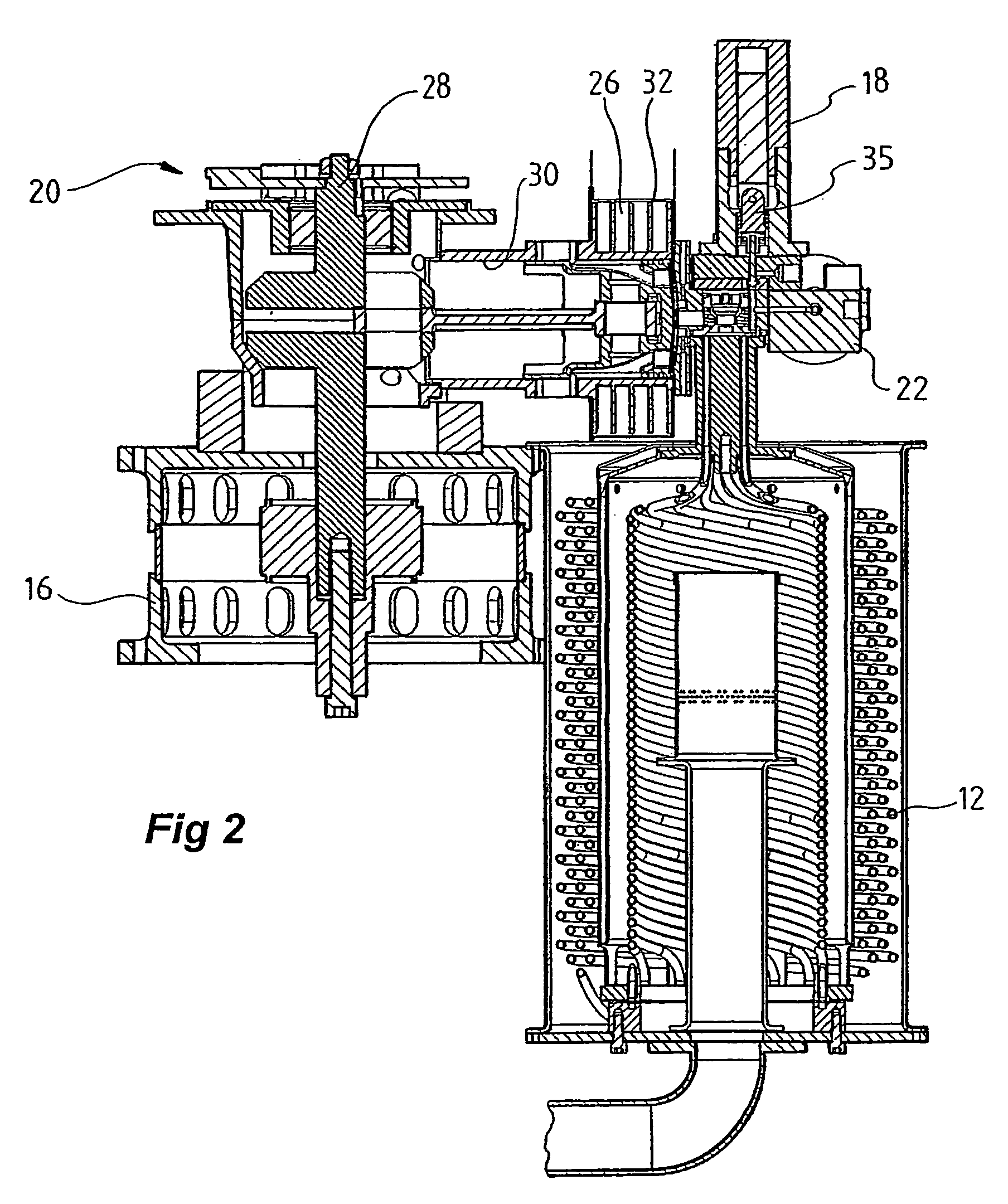
[0072]The engine 10 generally includes a boiler 12 suitable to generate the steam necessary for use as the working fluid and, for the preferred inlet system of the present invention, the secondary fluid. In this respect, a skilled addressee will appreciate that suitable flow passages for all aspects of the engine are not necessarily visible in all of the Figures. For example, a flow passage from the boiler 12 to the pilot valve in subsequent Figures is not evident in all cross-sections in the Figures, but of course is present in the engine.
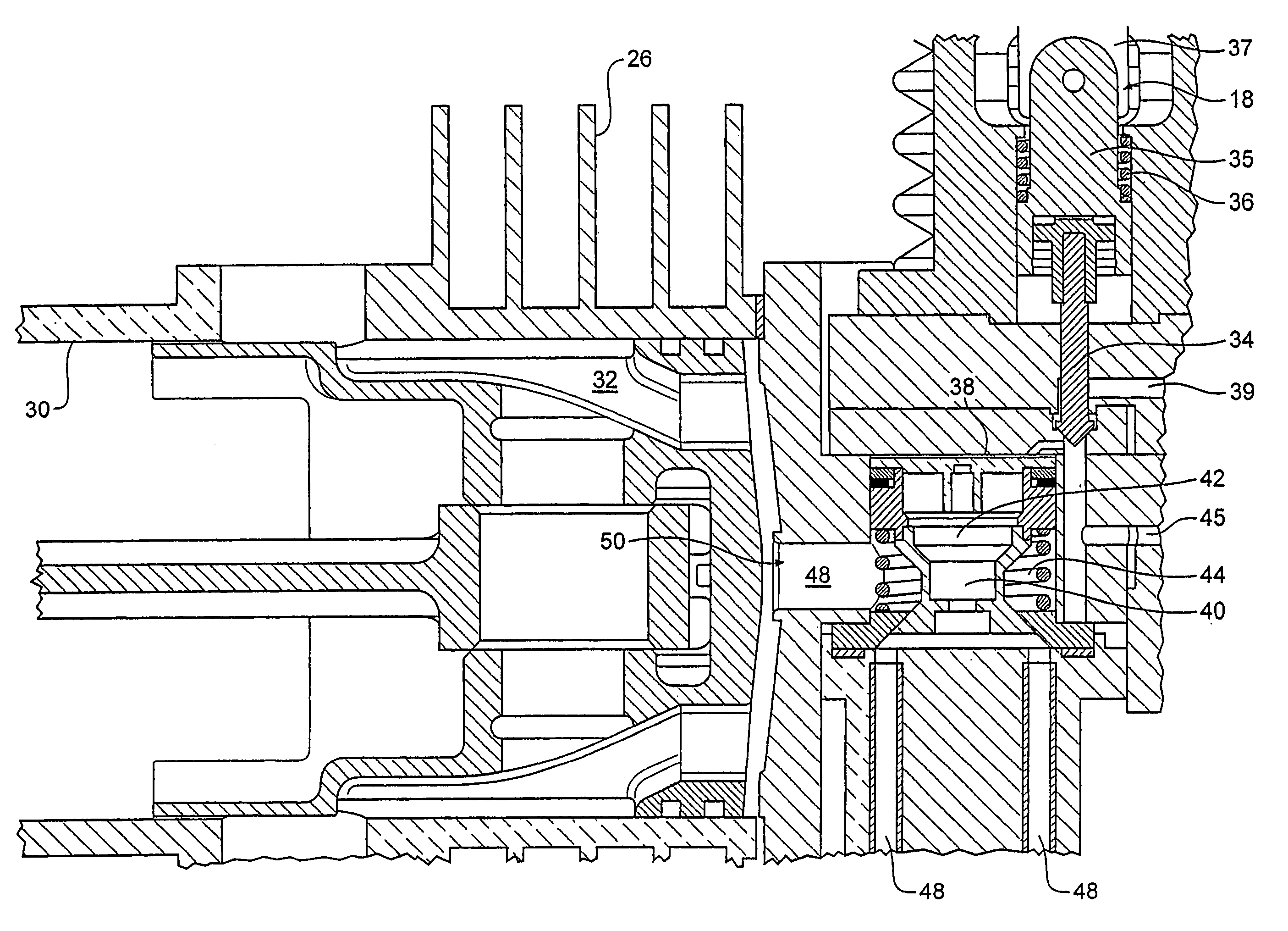
[0073]The engine 10 includes a reciprocating piston in a cylinder, with a variable volume expansion chamber, shown generally by reference numeral 14. The reciprocating piston is operatively connected to an el...
PUM
 Abstract
Description
Claims
Application Information