Electric lock with magnetic support of the coupling element

a technology of magnetic support and coupling element, which is applied in the direction of mechanical control devices, keyhole guards, limit/prevent/return movement of parts, etc., can solve the problems of high maintenance costs and more likely malfunctions, and achieve the effect of convenient manual operation

Inactive Publication Date: 2007-03-13
CISA
View PDF14 Cites 39 Cited by
  • Summary
  • Abstract
  • Description
  • Claims
  • Application Information

AI Technical Summary

Benefits of technology

[0007]The aim of the present invention is to obviate the above-mentioned drawbacks and to meet the mentioned requirements, by providing an electric lock with magnetic support of the coupling element that is constituted by a small number of simple elements, which can be easily operated manually in case of failure of the electric power supply.
[0008]Within this aim, an object of the present invention is to provide an electric lock that is simple, relatively easy to provide in practice, safe in use, effective in operation, and has a relatively low cost.

Problems solved by technology

The apparatuses normally used to enable opening when the lock has received the correct access code are constituted by a plurality of components: the high complexity of the apparatus makes malfunctions more likely, and said malfunctions moreover entail high maintenance costs, indeed because of the need to disassemble and reassemble the many parts, which are often small.

Method used


Image

  • Electric lock with magnetic support of the coupling element
  • Electric lock with magnetic support of the coupling element
  • Electric lock with magnetic support of the coupling element

Examples


Embodiment Construction

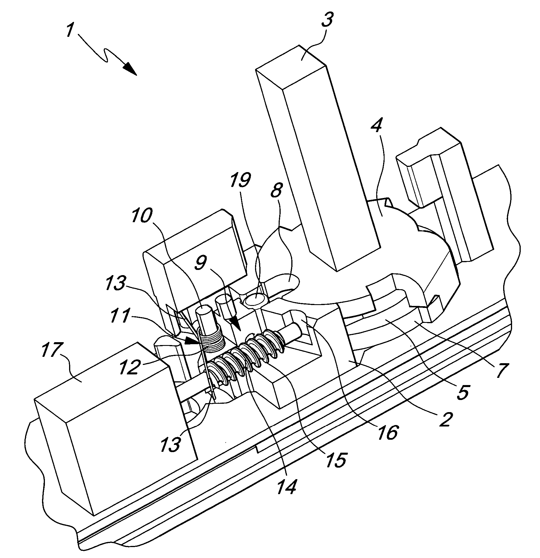
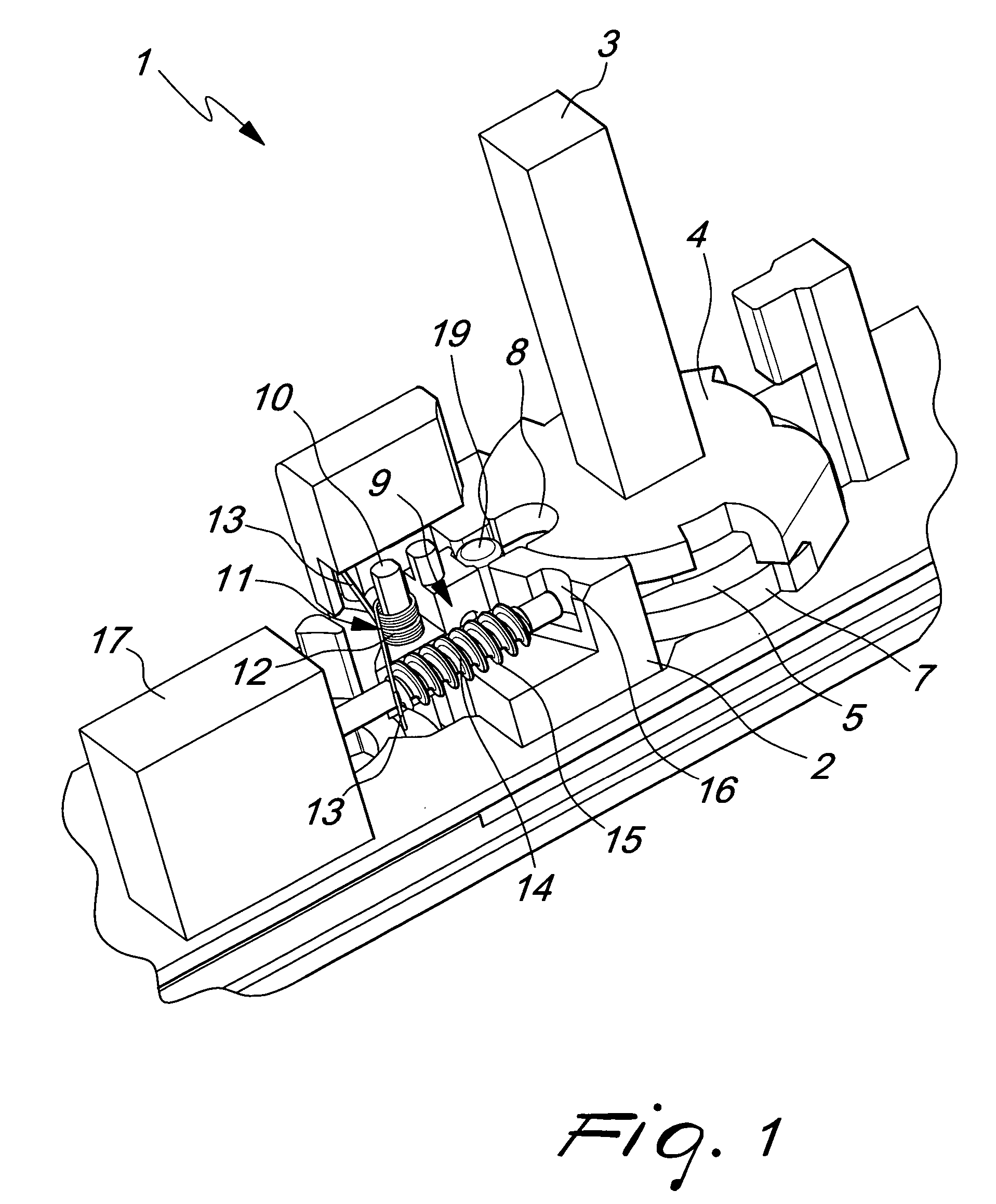
[0016]With reference to the figures, the reference numeral 1 generally designates an electric lock with magnetic support of the coupling element.

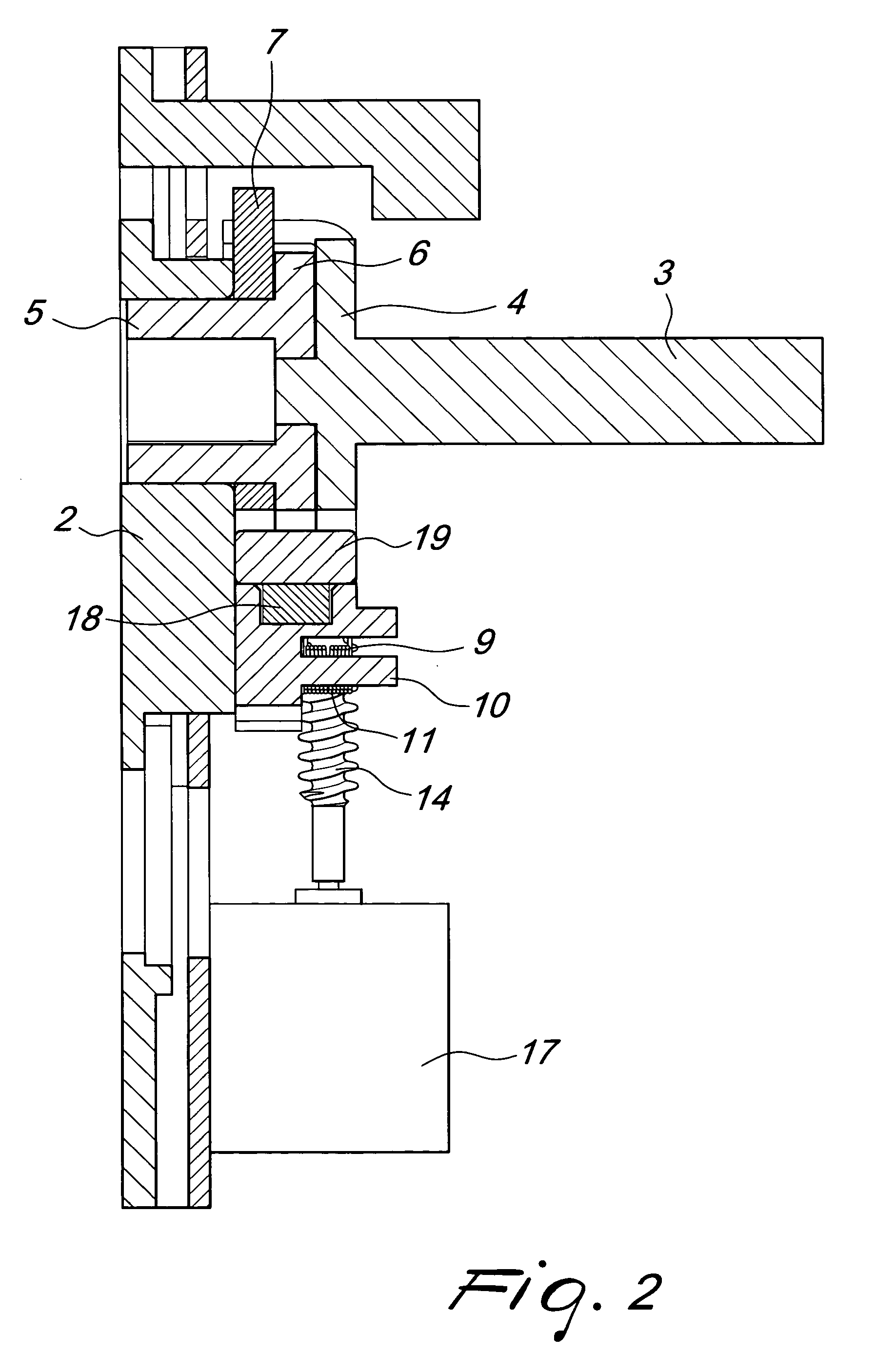
[0017]Each lock 1 is constituted by a fixed body 2, from which a stem 3 protrudes outward (the knob or handle for opening from the outside is connected to said stem). The stem 3 has, at its base, a plate 4, which can rotate on a sleeve 5, the upper edge 6 of which rests on a contrast plate 7. The sleeve 5 is associated with the locking element, not shown in the figure, and therefore a rotation thereof entails a corresponding retraction (or protrusion) of said locking element; the sleeve 5 is constantly associated with the internal handle.

[0018]The plate 4, the contrast plate 7 and the sleeve 5 have respective notches 8, which are substantially shaped in a similar manner.

[0019]With respect to the assembly configuration, a slider 9 is located below the plate 4 and the sleeve 5, can slide on a respective linear guide, and is provided with a cy...


PUM


Abstract

An electric lock with magnetic support of the coupling element, comprising a locking element engaging a selvage, a decoding assembly for a code bearing component, an actuation element, connected to an internal handle and associated with the locking element, and a second actuation element, connected to an external handle and coupled to the locking element by way of an electromechanical device. The actuation element comprises a stem connected to the external handle with a rotating plate and a contrast plate, at an end resting freely on a rotatable sleeve, coupled to the locking element and provided with notches; an electric motor and a slider, aligned with the notches actuatable to perform translational motion, and a magnet supporting a coupling element adapted to enter the notches to rigidly couple to each other the plate, the contrast plate and the sleeve.

Description

[0001]The present invention relates to an electric lock with magnetic support of the coupling element.BACKGROUND OF THE INVENTION[0002]Electrically operated locks suitable to be applied to doors for accessing spaces such as rooms, offices and apartments use a component that is provided with a code as an access key.[0003]This component is generally a card that can contain a microprocessor or can be provided with a magnetic strip: in any case, its purpose is to store a code that is correlated to the lock to be operated.[0004]The door protected with this type of lock generally has an internal handle (or knob), which acts directly on the locking element of the lock, always allowing to open said lock from the inside.[0005]For access from the outside, it is necessary to insert the card in an appropriately provided reader (or, more generally, to insert the component in an appropriately provided receptacle of a respective decoding assembly), which enables a handle (or knob), located on the ...

Claims


Application Information

Patent Timeline
Patent Type & Authority Patents(United States)
IPC IPC(8): E05B49/00E05B55/04E05B15/04E05B47/00E05B47/06E05B63/00
CPCE05B47/0692E05B63/0069E05B47/0012E05B47/0038E05B2047/0084E05B2047/0016E05B2047/0028E05B2047/0031E05B2015/0496Y10T70/5823Y10T70/713Y10T70/5394Y10T70/7102Y10T70/7057Y10T70/5805
Inventor ERRANI, DEODARCHINI, LUCIANO
Owner CISA
Why Eureka
Try Eureka