Medical fastener and tool

a fastener and tool technology, applied in the field of threaded fasteners, can solve the problems of reducing purchase, reducing visibility, cutting, and causing the blade to spin out of the slot, and reducing the angular excursion of the fastener

Active Publication Date: 2007-03-13
ATLAS SPINE
View PDF46 Cites 49 Cited by
  • Summary
  • Abstract
  • Description
  • Claims
  • Application Information

AI Technical Summary

Benefits of technology

[0011]Disclosed is a drive system for a surgical fastener or other screw fastener. The drive tool includes a drive tip that mates closely with the recess formed in the head of a threaded fastener. The surgical fastener has a head with a quadrilobe fitting therein which closely mates with the quardilobe tip of the tool. The cooperating drive surfaces align the fastener and tool coaxially and produce four point contact equidistant about the circumference of said fastener significantly reducing angular excursions of the fastener during placement in the bone.
[0013]It is a further objective of this invention to provide increased surface contact between the fastener and the tool during rotation of the system.
[0014]It is another objective of this invention to provide a cooperating connection which resists angular excursions between the tool and fastener during rotation of the system by directing rotational forces in a plane perpendicular to the axis of the connection.
[0015]It is a still further objective of this invention to provide guiding and centering surfaces on the tool and the fastener for ease in joining the tool and the fastener as well as providing a transition area between the central axis and the contact surfaces.

Problems solved by technology

Further, as the screw tightens to form a fastening, the increasing torque causes the blade to spin out of the slot.
In surgery, the operating field is as small as possible and usually very confined which may restrict the approach of various tools to a less than optimum angle to the work area, producing side loads and reduced visibility, among other things, when placing a threaded fastener.
Any wobble of the alignment of the fastener can lessen the purchase of the threaded fastener with the bone and significantly reduce the holding power of a threaded fastener.
In addition, the socket has a significant depth required by the triangular contact surfaces.
However, the tapered form of the interconnection produces a tendency for the driving tool to spin-out of the recess under heavy torque forces.

Method used


Image

  • Medical fastener and tool
  • Medical fastener and tool
  • Medical fastener and tool

Examples


Embodiment Construction

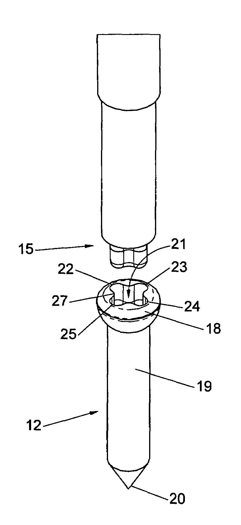
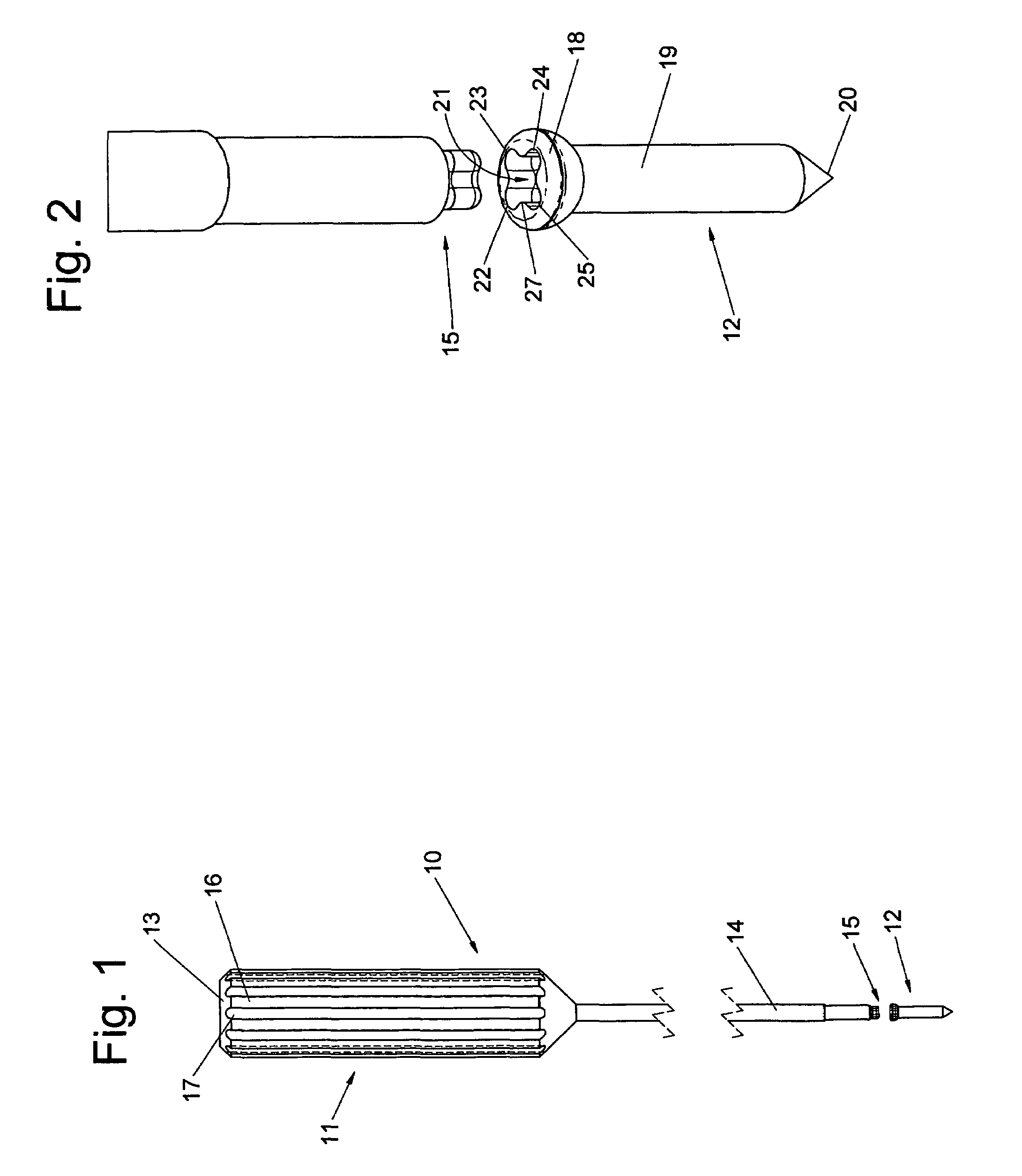
[0026]The drive system 10, shown in FIG. 1, is illustrated as a hand tool 11 and a fastener 12. The hand tool has a grip 13 and a shaft 14 terminating in the cooperating tip 15. The grip 13 is constructed, for example, with alternating lands 16 and grooves 17 to improve the non-slip manipulation and rotation of the tool during driving of the fastener 12. However, the shaft 14 may have a chuck rather than a handle for use with power tools.

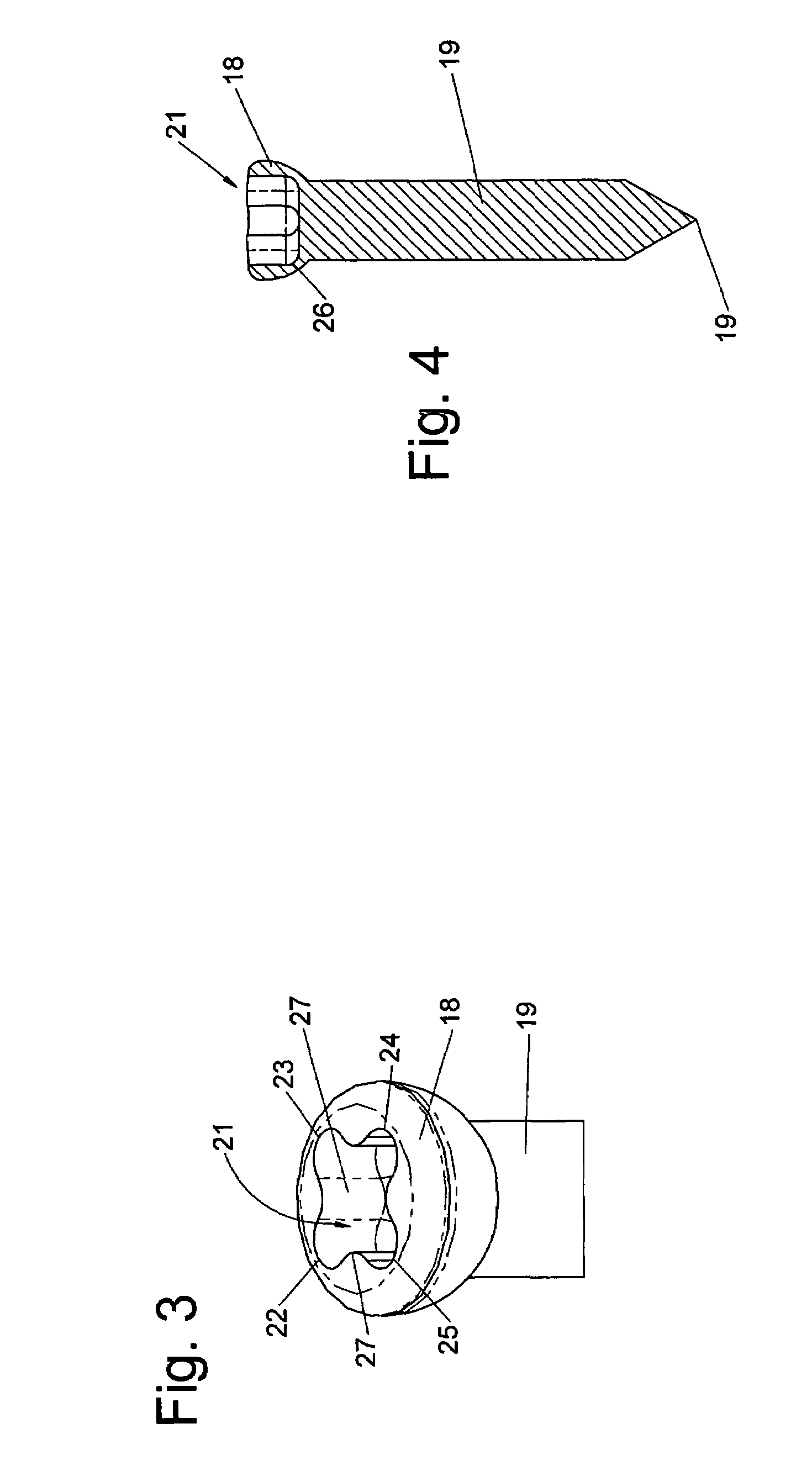
[0027]The fastener 12, in the preferred embodiment, is a surgical screw with a helical screw thread extending from the head 18 along the shank 19 to the leading end 20. There are numerous thread designs all of which are directed to increasing the purchase of the screw.

[0028]Further, there are self-tapping screws and screws used in pre-drilled holes. These latter types are directed to driving the screw without burring the bone-screw thread pattern. These screws reduce the wobble or angular excursions from the longitudinal axis produced by the side lo...


PUM


Abstract

A drive system for a surgical fastener is composed of a drive tool with a drive tip that mates closely with the recess formed in the head of a threaded fastener. The surgical fastener has a head with a quadrilobe fitting therein which closely mates with the quardilobe tip of the tool. The cooperating drive surfaces align the fastener and tool coaxially and produce four point contact equidistant about the circumference of said fastener significantly reducing angular excursions of the fastener during placement in the bone.

Description

BACKGROUND OF THE INVENTION[0001]1. Field of the Invention[0002]The invention relates generally to threaded fasteners and fastener drives for the fasteners which make up a fastener drive system. The fastener drive system of this invention is especially useful in the medical arts which require that the fastener be oriented on the end of a drive tool in a coaxial position to eliminate any angular excursions between a prosthesis, the bone and the fastener.[0003]2. Description of the Prior Art[0004]There is a great deal of prior art teaching various forms of drive systems where one component is termed female and the other component is termed male with a cooperating recess and projection, respectively. Probably, the most common is the slotted screw head formed to accept the blade of a screw driver. Almost everyone knows that the tolerance between the slot and the blade is such that small side loads will turn the screw and disconnect the screw driver thereby creating a bore in the support...

Claims


Application Information

Patent Timeline
Patent Type & Authority Patents(United States)
IPC IPC(8): B25B23/00F16B23/00B25B13/48
CPCF16B23/003B25B15/005A61B17/8875A61B17/861
Inventor BAYNHAM, MATTHEW G.
Owner ATLAS SPINE
Why Eureka
Try Eureka