Ocular surgical protective shield

Active Publication Date: 2007-03-13
OCULO PLASTIK
View PDF6 Cites 41 Cited by
  • Summary
  • Abstract
  • Description
  • Claims
  • Application Information

AI Technical Summary

Benefits of technology

[0005]The present invention is a device that shields a person's eyes from different forms of radiation. The invention is illustrated primarily as used for eye protection from laser energy, however, it is to be understood that the present invention can be used to protect a person's eyes from all forms of radiation energy including the sun, as well as all forms of medical treatment radiation energy including but not limited to lasers, radio frequencies, medical dermabrasion granules, micro waves, and intense pulse light. The eye shields have an external surface that absorbs any laser energy that hits the shield. The shields are connected to each other by a nose piece and the nose piece is connected to each shield by a mounting means. The mounting means is combined with the nose piece securely enough that involuntary movement of the nose piece relative to the shields is retarded, while voluntary movement of the nose piece is allowed. The shields and nose piece can be made of metal or plastic, depending on what procedure is being performed and what type of energy is being used. The nose piece can pivot through a range of positions using the mounting means as its pivot point. This displacement of the nose piece is desirable so that the nose piece does not block a specialist's access to any particular area of the patient's face. However, as the specialist displaces the nose piece, the shields do not change their position on the patient's face which could allow radiant energy to inadvertently pass under the shields and into the patient's eyes. In order to keep the shields stationary as the nose piece is moved, each mounting is positioned substantially perpendicular to its shield and the mounting on the first shield is positioned parallel to the mounting on the second shield so that the mounting on the first shield is a mirror image of the mounting on the second shield. This alignment allows the nose piece to be displaced upward toward the patient's forehead and downward toward the patient's chin without affecting the fit or position of the shields over the patient's eyes. As will be obvious from the description below, many of the means used to connect the nose piece with the shields can also be used in the temporal area of the shields to connect the shields to the headband which holds the shields to the patient's face.

Problems solved by technology

However, as the specialist displaces the nose piece, the shields do not change their position on the patient's face which could allow radiant energy to inadvertently pass under the shields and into the patient's eyes.

Method used


Image

  • Ocular surgical protective shield
  • Ocular surgical protective shield
  • Ocular surgical protective shield

Examples


Embodiment Construction

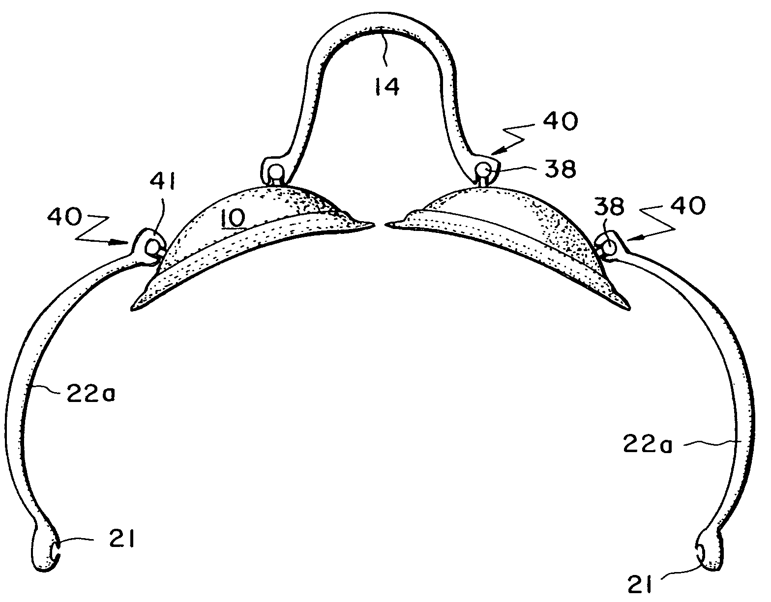
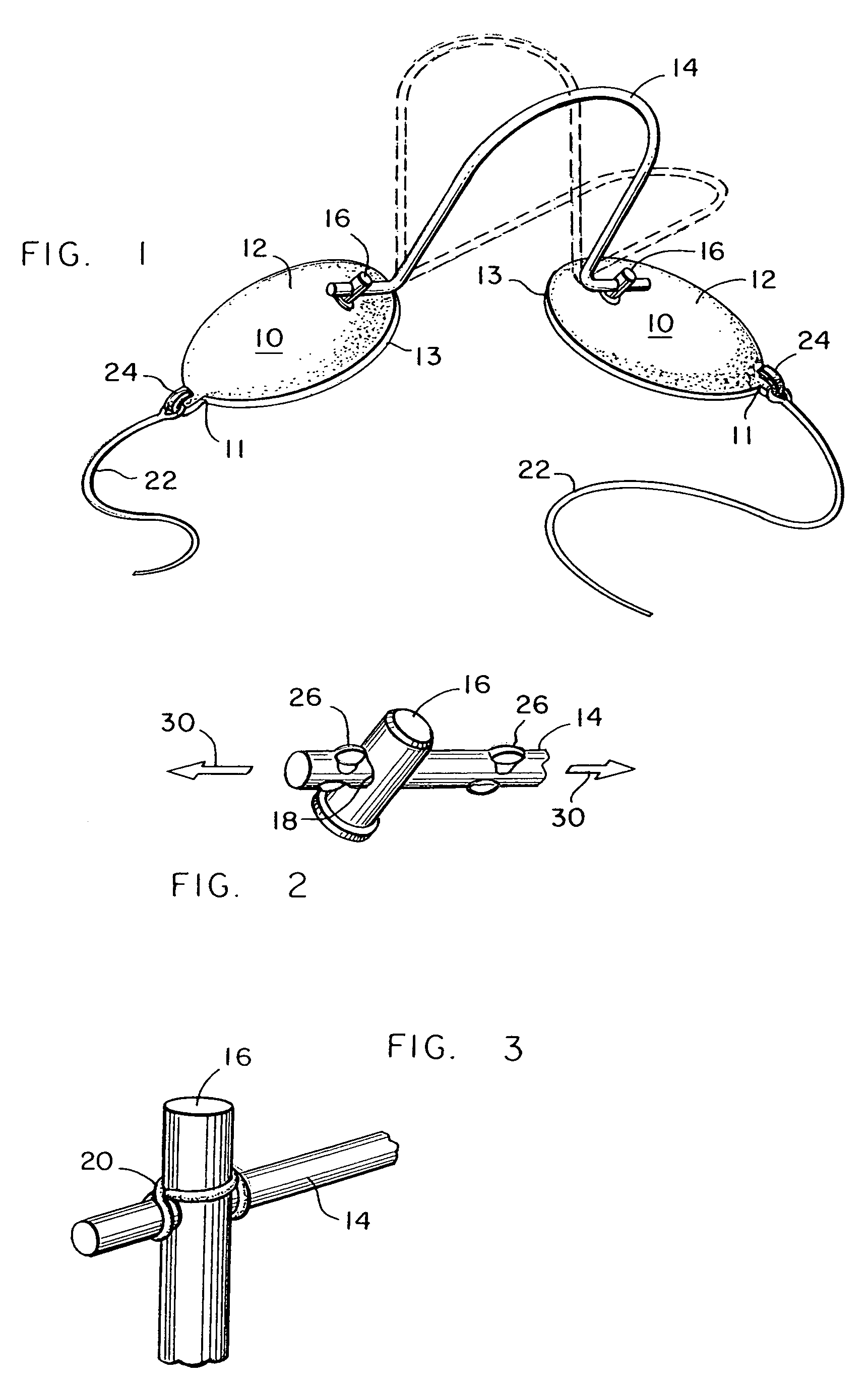
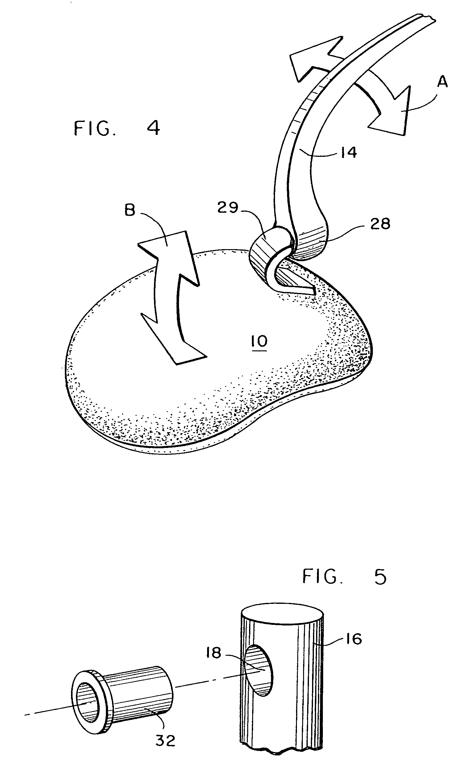
[0030]FIG. 1 shows how the external ocular shield device is comprised of two shields 10 connected by a nose piece 14. The shields 10 and nose piece 14 can be made of metal, plastic, or a combination of metal and plastic, depending on which procedure is being preformed and which type of energy is being used. Each shield 10 is sized and shaped so that it will cover the entire eye. Each shield 10 comprises an outer temporal area 11 and an inner nasal area 13, and can further comprise an elastomeric lip 46 (shown in FIG. 18) that can be molded onto the shields 10 so as to provide a comfortable and precise fit around the patient's eyes. The elastomeric lip 46 further serves to keep any heat energy that may build up on the shield 10 from contacting the patient's skin. The shields 10 are approximately 1 mm 4 mm thick and are constructed of a material that does not allow medical treatment radiation energy to pass through. In one embodiment the shields are constructed of a metal such as stai...


PUM


Abstract

External ocular shields for protecting a patient's eyes from medical treatment radiation energy such as a laser during a medical procedure. Each shield has an external surface that absorbs energy that hits the shield. The shields are connected to each other by a nose piece, and the nose piece is connected to each shield by a mounting means. The mounting means are positioned perpendicular to the shields and parallel to each other so that the nose piece can pivot upward towards the user's forehead and downward towards the user's chin without altering the fit of the shields over the user's eyes.

Description

BACKGROUND OF INVENTION[0001]Lasers and other various energy types are being used with increasing frequency in a variety of medical procedures. Although lasers make many procedures easier, less painful, and more precise, there are also certain risks associated with using lasers on patients. A primary risk associated with using lasers is the danger of getting laser light in a person's eyes. Even a brief shot of laser light into a person's eyes can cause serious damage and even blindness. Another risk associated with high powered energy devices is that the radiant energy may hit the eye shield and transform into heat energy, thus burning the patient where the eye shield contacts the patient's skin. In medical procedures a specialist must be careful that an inadvertent beam of radiation does not enter a patient's eyes or hit the shield repeatedly to cause the shield to heat up, especially if the specialist is working on a patient's head or face.[0002]In order to minimize this risk, ocu...

Claims


Application Information

Patent Timeline
Patent Type & Authority Patents(United States)
IPC IPC(8): A61F9/00A61F9/04
CPCA61F9/04
Inventor DURETTE, JEAN-FRANCOIS
Owner OCULO PLASTIK
Why Eureka
Try Eureka