Device for establishing noise in a motor vehicle

a technology for establishing noise and motor vehicles, which is applied in the direction of casings/cabinets/drawers, instruments, casings/cabinets/drawers, etc., can solve the problems of low efficiency, a certain susceptibility to failure, and the inability to offer the optimum solution, so as to achieve the effect of easy mounting

a technology for establishing noise and motor vehicles, which is applied in the direction of casings/cabinets/drawers, instruments, casings/cabinets/drawers, etc., can solve the problems of low efficiency, a certain susceptibility to failure, and the inability to offer the optimum solution, so as to achieve the effect of easy mounting

US7188703B2Inactive Publication Date: 2007-03-13DAIMLER AG

Image

  • Device for establishing noise in a motor vehicle
  • Device for establishing noise in a motor vehicle
  • Device for establishing noise in a motor vehicle

Examples


Embodiment Construction

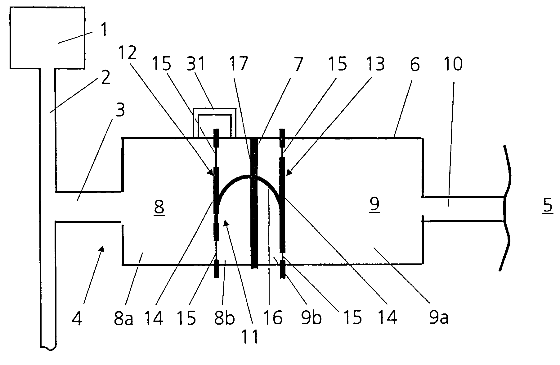
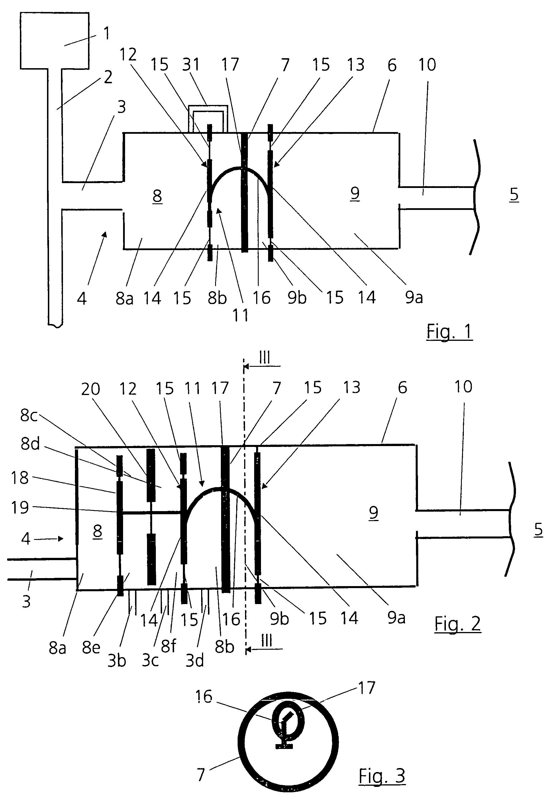
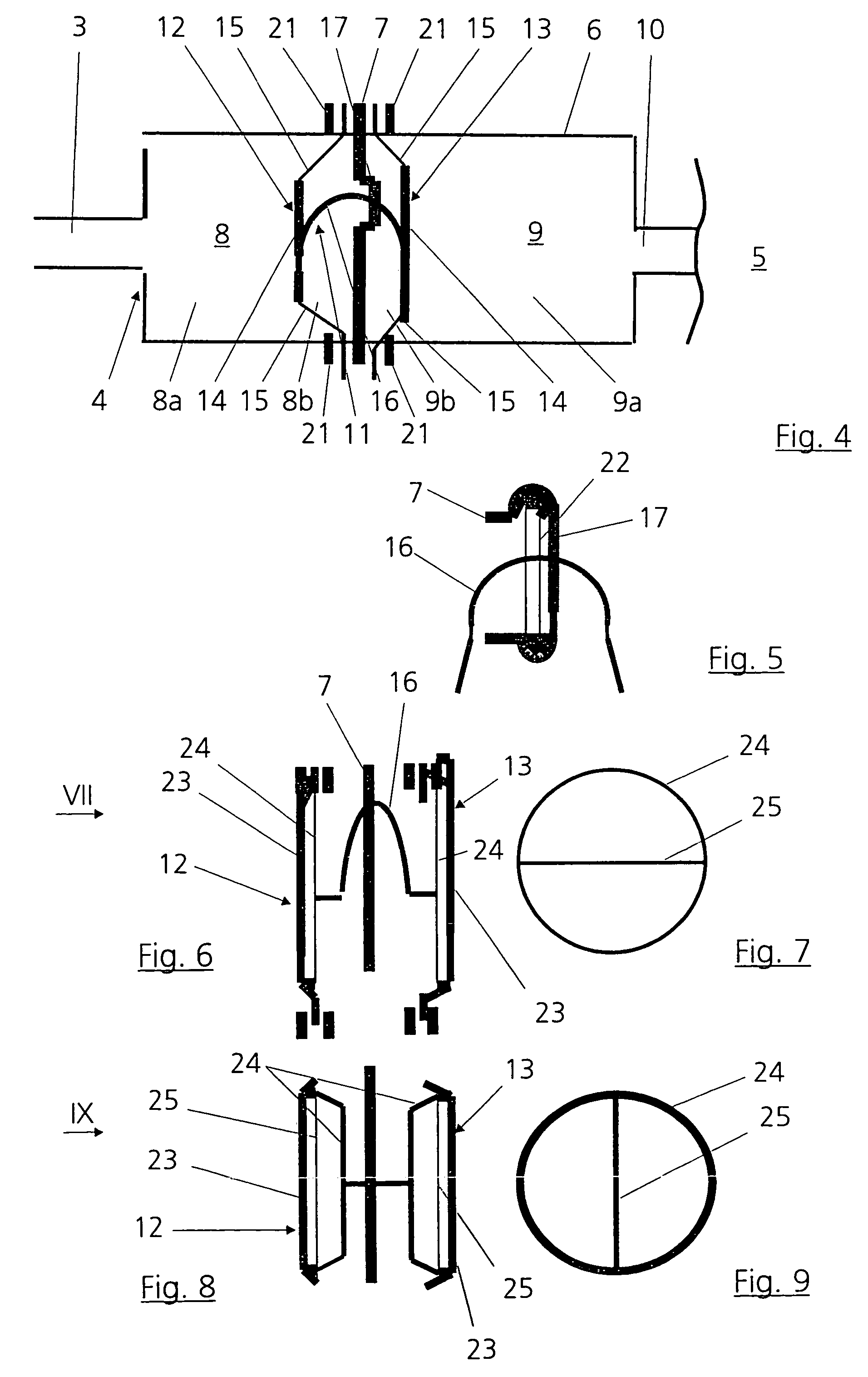
[0028]FIG. 1 shows an intake line 2, leading to an internal combustion engine 1, that is, a gas-carrying line which is connected via an inlet line 3 to a device 4 for generating in the interior of a motor vehicle the noises produced by the engine 1. Instead of branching off from the intake line 2, the inlet line 3 may also branch off from some other gas-carrying line of the engine 1, that is for example from an exhaust line. Like the engine 1, the intake line 2 and the inlet line 3, the device 4 is located in a motor vehicle, which is not represented in its entirety. The device is capable of influencing both the noise in an interior space 5 of the motor vehicle and in the surroundings of the motor vehicle.

[0029]The device 4 has a housing or hollow body 6, which is subdivided by a wall 7 so as to form an inlet space 8 and an outlet space 9. The wall is acoustically substantially inactive that is to say does transmit the sound from the inlet space 8 to the outlet space 9. The inlet sp...


PUM


Abstract

In a device for establishing noise in a motor vehicle, including a housing having an inlet space, which is in communication via an inlet line with a gas-carrying part of an internal combustion engine arranged in the motor vehicle, and an outlet space, which is acoustically coupled by means of an outlet line to an interior space of the vehicle or the space surrounding the vehicle, the inlet space is separated from the outlet space at least by an acoustically substantially inactive wall. Arranged inside the housing is a sound transmission device, which has vibratable elements, one arranged in the inlet space and onother arranged in the outlet space and connected to each other by a curved connecting element, which is mounted on the acoustically inactive wall, for the transmission of sounds introduced through the inlet line into the inlet space to the outlet space.

Description

[0001]This is a Continuation-In-Part Application of International Application PCT / EP03 / 03117 filed Mar. 26, 2003 and claiming the priority of German application 102 23 873.1 filed May 29, 2002.BACKGROUND OF THE INVENTION[0002]The invention relates to a device for establishing noise in a motor vehicle including an internal combustion engine. The device includes a housing with an inlet space in communication, via an inlet line, with a gas carrying part of the internal combustion engine and an outlet space which is acoustically coupled by an outlet line to the interior of the motor vehicle.[0003]Such a device is known, for example, from DE 44 35 296 A1. With such devices, the noises produced by the internal combustion engine are to be transmitted more intensely to the driver of the motor vehicle, in particular during acceleration, in order to provide, on one hand, for a more intensive driving experience and, on the other hand, to provide more information concerning the load state of th...

Claims


Application Information

Patent Timeline
13 Mar 2007
Publication
US7188703B2
IPC
F01N1/16; B60Q5/00; B60Q9/00; G08B3/02; G10K11/22; F02M35/10; H05K5/02; F01N1/08; G10K9/02; G10K9/04; G10K15/04
CPC
G10K9/02; G10K15/04; G10K11/22; G10K9/04
Inventors
HOFMANN, MARCUS; STAROBINSKI, ROUDOLF