Mobile plating system and method

a technology of deposition technology and plating system, which is applied in the direction of programmed manipulators, conveyor parts, ammunition loading, etc., can solve the problems of large, complex, expensive and complex systems, complex piping and plumbing, and complex vacuum systems, and achieves reduced or eliminating shipping costs, substantial expense and cost, and eliminates unacceptable risks due to possible shipping delays or lost shipments

Inactive Publication Date: 2007-03-13
NOVA MACHINE PRODS
View PDF74 Cites 14 Cited by
  • Summary
  • Abstract
  • Description
  • Claims
  • Application Information

AI Technical Summary

Benefits of technology

[0012]Another technical advantage of the present invention includes the capability to make coating or plating from deposition technologies available for large and bulky components and parts that cannot be shipped or cannot be easily shipped without having to incur the significant expense of designing, operating, and maintaining a complex system using deposition technology.
[0013]Yet another technical advantage of the present invention includes the capability to coat or plate mission critical components, such as reactor vessel head studs used at nuclear power plants. Because the present invention allows deposition technologies to be brought to the customer, unacceptable risks due to possible shipping delays or lost shipments are eliminated.
[0014]Another technical advantage of the present invention includes the capability to reduce or eliminate shipping costs, even for smaller components and parts or non-mission critical parts, and eliminate the need to incur the substantial expense and cost of designing, operating, and maintaining a complex system using deposition technology. This significantly reduces overall costs.
[0015]Still yet another technical advantage of the present invention includes the capability to operate noisy mechanical vacuum pumps, such as mechanical roughing and foreline pumps, external to the mobile chamber resulting in reduced mechanical vibrations and increased operational reliability of the mobile plating system.
[0016]Still yet another technical advantage includes the capability to use sophisticated cooling system, such as a water cooling system, within a mobile storage volume of the mobile plating system.
[0017]Yet another technical advantage includes the capability to use sophisticated deposition technology without producing or leaving behind any harmful waste byproducts. This is significant.

Problems solved by technology

Such deposition technologies involve large, expensive, and complex systems, equipment, and machinery.
For example, many such deposition technologies require an expensive, bulky, and complex vacuum system to establish and maintain a vacuum at a designated operating pressure.
Such complex piping and plumbing is particularly subject to leakage at turns in the pipes or joints where pipes interface due to interface problems and mechanical vibrations caused by the operation of the vacuum pumps.
Some or all of the vacuum pumps, such as a diffusion pump, may also require a large and complex cooling system that, often, uses hundreds or thousands of gallons of water that must be cooled and circulated prior and during the operation of the vacuum pump.
This may require a large and bulky water cooling system that includes a large water storage tank and a refrigeration system to cool the water in the large storage tank.
Because deposition technologies involve such large, expensive, and complex systems, equipment, and machinery, such systems must, generally, be permanently installed at a location.
Unfortunately, because this is such an expensive option, it is often cost prohibitive.
The high expenses include, not only the cost in procuring the real estate and equipment, and in setting up such complex systems, but in maintaining the equipment and in hiring and employing personnel with the special expertise needed to successfully operate and maintain such systems.
Problems also exist in designing a deposition technology system.
As has been illustrated, the design, installation, operation, and maintenance of deposition technology systems are complex and expensive, and, as a result, the coating or plating of large and bulky components using deposition technologies is often not available, even though such large and bulky components may greatly benefit from the significant advantages offered by such deposition technologies.
In some cases, the availability of certain components or parts is so critical that, from either a safety and / or a financial standpoint, the risk of a shipping delay or lost shipment, no matter how small, is too great a risk to take, even if significant advantages could be gained through coating or plating.
For example, a reactor vessel head stud that is used in a nuclear power plant is so crucial and unique, that the risk of a shipping delay or lost shipment during a plant outage, such as, for example, during a fuel reload at a nuclear power plant that occurs every couple of years or so, is too great to take.
For example, for every day that a nuclear plant is kept off line because of a delay, hundreds of thousands or even millions of dollars may be lost.

Method used


Image

  • Mobile plating system and method
  • Mobile plating system and method
  • Mobile plating system and method

Examples


Embodiment Construction

[0029]It should be understood at the outset that although an exemplary implementation of the present invention is illustrated below, the present invention may be implemented using any number of techniques, whether currently known or in existence. The present invention should in no way be limited to the exemplary implementations, drawings, and techniques illustrated below, including the exemplary design and implementation illustrated and described herein.

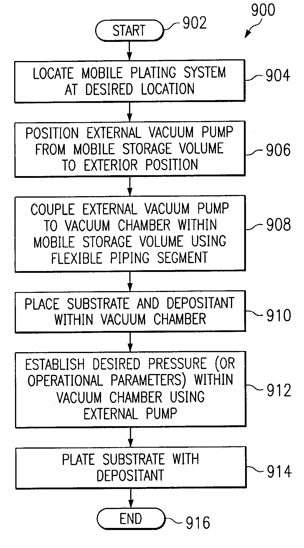
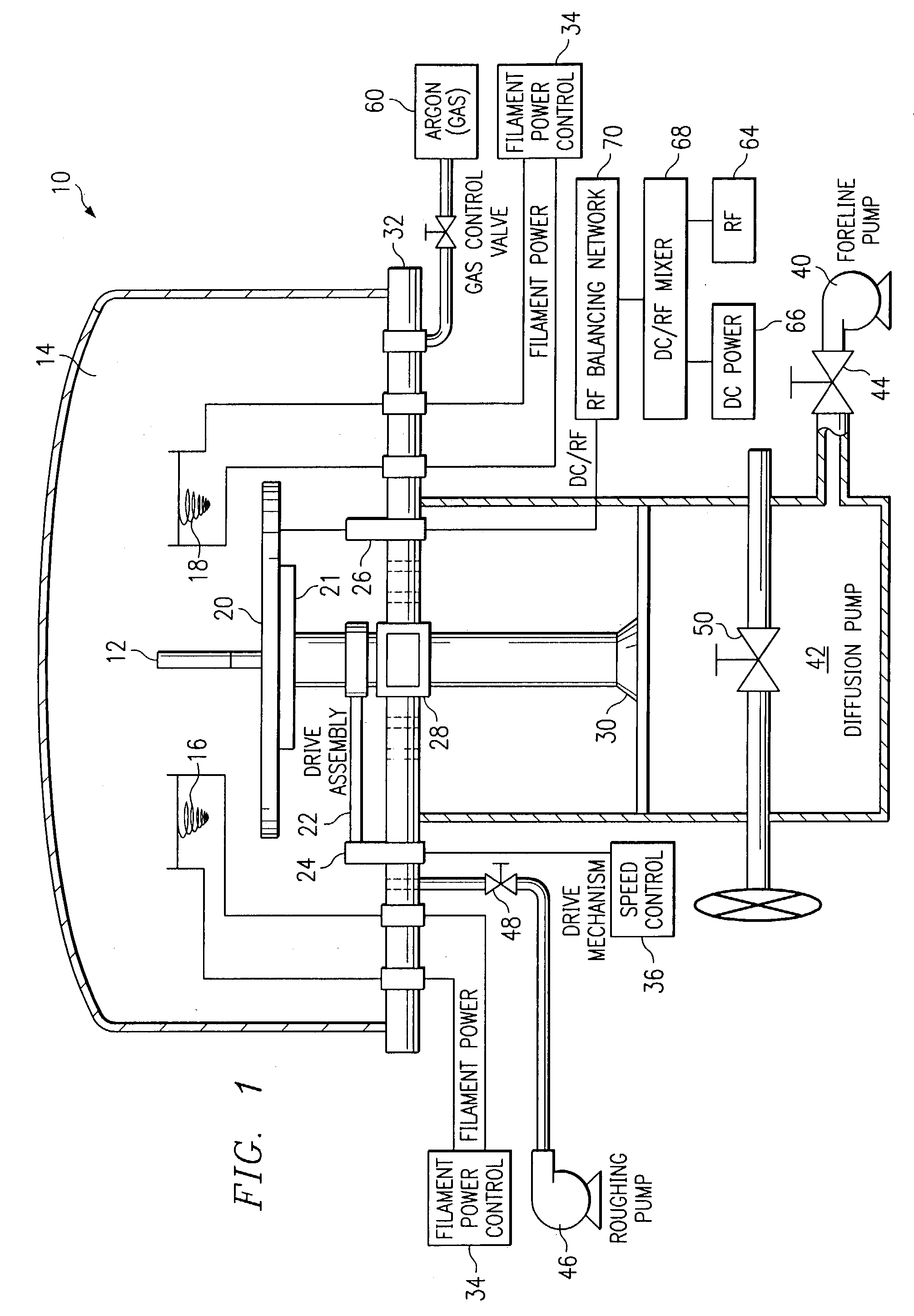
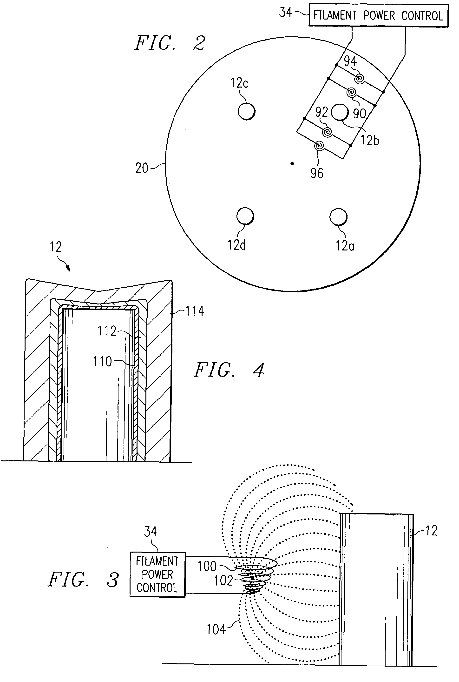
[0030]Initially, a system and method for plasma plating is described in detail below in connection with FIGS. 1-6 to illustrate a type of deposition technology that may be used with the mobile plating system and method. Although it should be understood that the present invention is in now way limited to the exemplary plating or deposition technology illustrated and discussed in connection with FIGS. 1–6, and that the present invention may be used with virtually any known or available plating or deposition technique. Finally, an embod...


PUM

PropertyMeasurementUnit
thicknessesaaaaaaaaaa

Abstract

An exemplary method for using a mobile plating system is provided that includes locating the mobile plating system at a desired location for plating, positioning an external vacuum pump from an interior position of a mobile storage volume of the mobile plasma plating system to an exterior position, and coupling the external vacuum pump to a vacuum chamber within the mobile storage volume of the mobile plasma plating system using a flexible piping segment, rigid coupling with a dampening effect, or other arrangement operable to reduce and / or eliminate the mechanical vibrations within the vacuum chamber due to the operation of the external vacuum pump.

Description

RELATED APPLICATIONS[0001]This application is a divisional application of U.S. patent application Ser. No. 09 / 576,640, entitled Mobile Plating System and Method, naming Jerry D. Kidd, Craig D. Harrington, and Daniel N. Hopkins as inventors, filed May 22, 2000, now U.S. Pat. No. 6,503,379. This application does not claim priority from but is related to U.S. patent application Ser. No. 09 / 427,775 entitled System and Method for Plasma Plating, filed Oct. 26, 1999, and named Jerry D. Kidd, Craig D. Harrington, and Daniel N. Hopkins as joint inventors, and U.S. patent application Ser. No. 09 / 578,166, entitled Configurable Vacuum System and Method, filed May 22, 2000, now U.S. Pat. No. 6,521,104, and named Jerry D. Kidd, Craig D. Harrington, and Daniel N. Hopkins as joint inventors.TECHNICAL FIELD OF THE INVENTION[0002]This invention relates in general to the field of mobile systems and deposition technology for plating and coating materials and more particularly to a mobile plating syste...

Claims


Application Information

Patent Timeline
Patent Type & Authority Patents(United States)
IPC IPC(8): C23C16/00C23C14/24C23C14/32C23C14/34C23C14/56C23C16/44
CPCC23C14/56C23C14/32C23C14/00
Inventor KIDD, JERRY D.HARRINGTON, CRAIG D.HOPKINS, DANIEL N.
Owner NOVA MACHINE PRODS
Why Eureka
Try Eureka