Fuel cell system
a fuel cell and system technology, applied in the field of fuel cell systems, can solve the problem of high energy consumption and achieve the effect of reducing energy consumption
- Summary
- Abstract
- Description
- Claims
- Application Information
AI Technical Summary
Benefits of technology
Problems solved by technology
Method used
Image
Examples
first embodiment
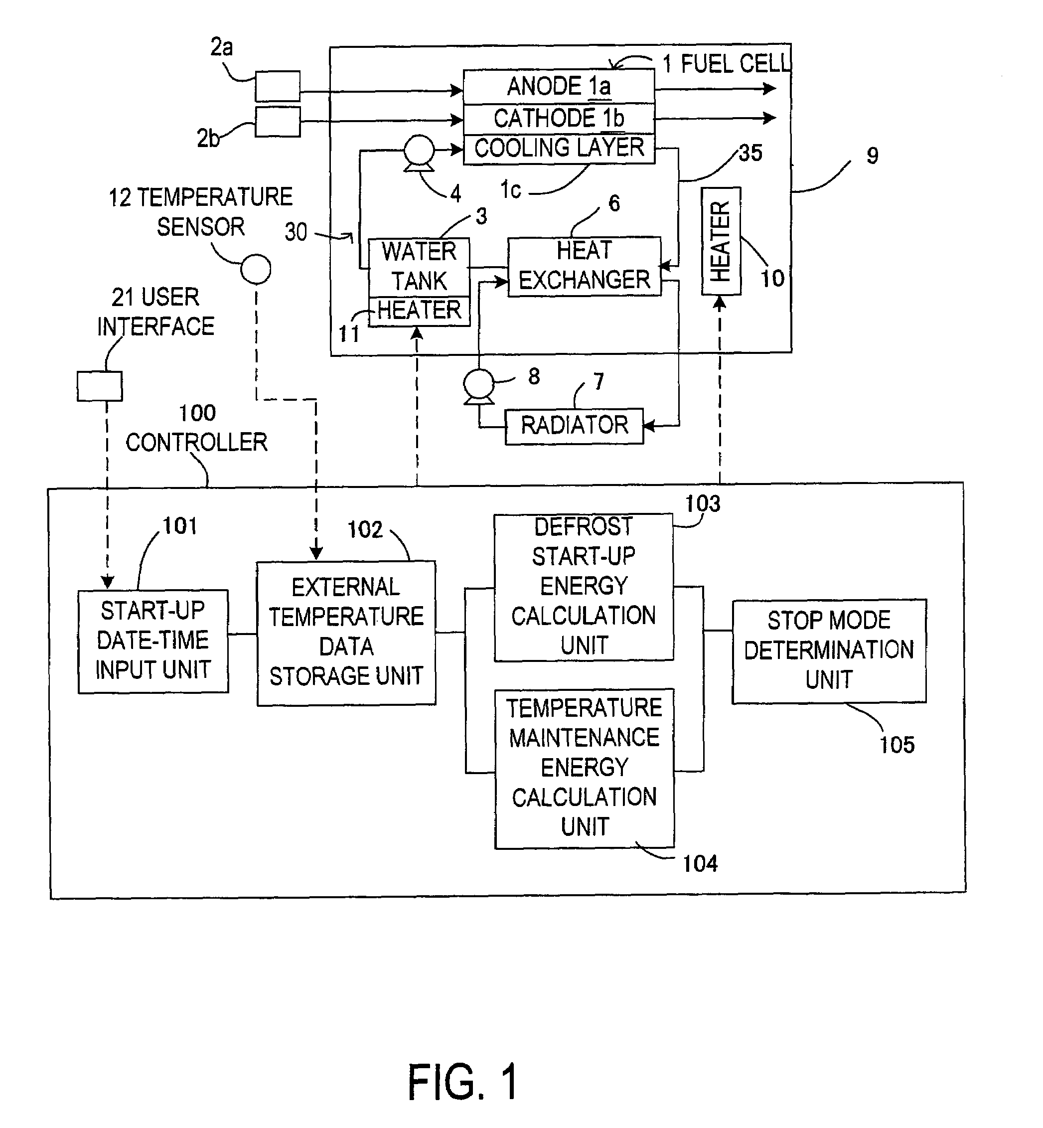
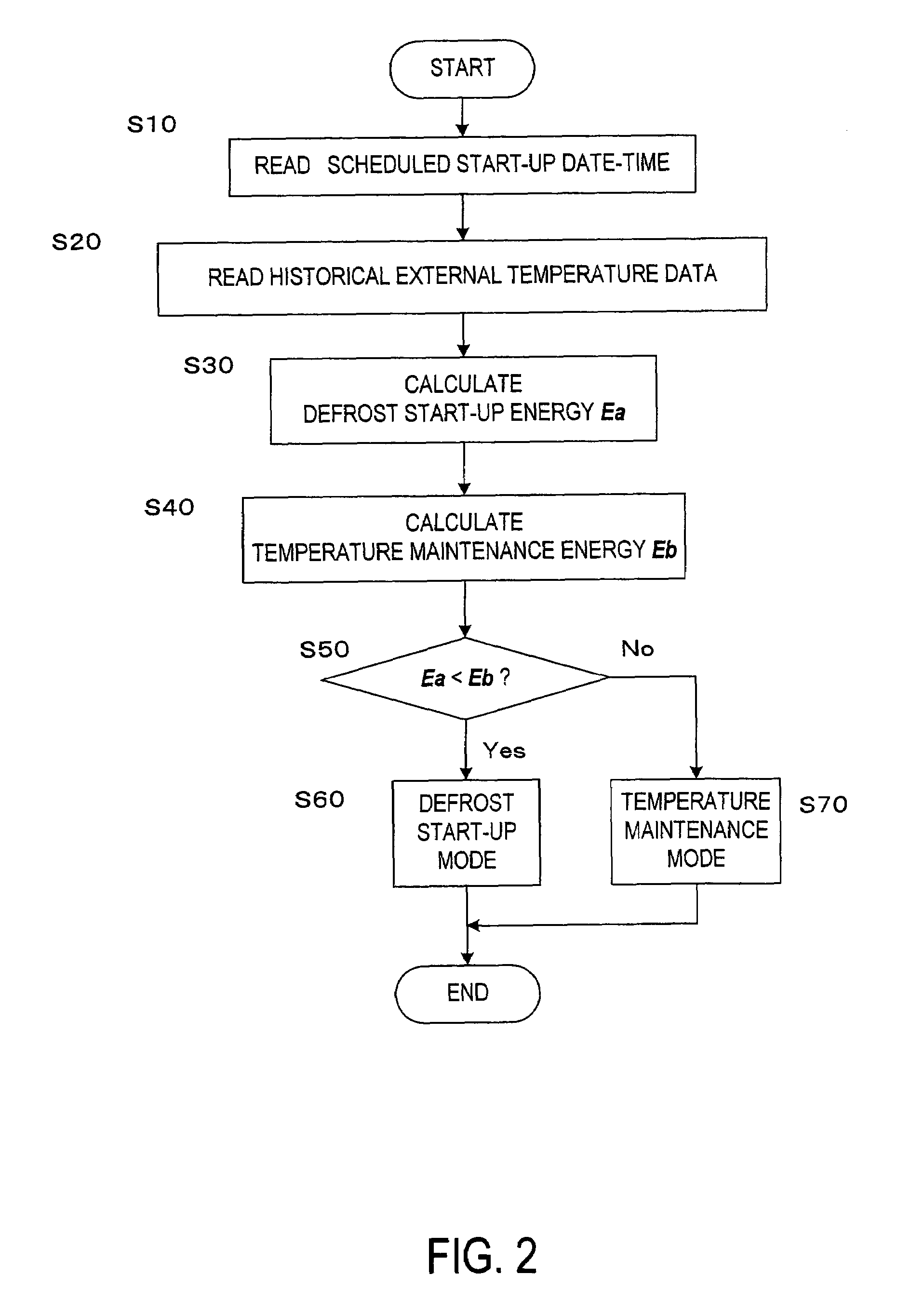
[0041] the defrost start-up energy calculation unit 103 includes a program module corresponding to the step S30. The defrost start-up energy calculation unit 104 includes a program module corresponding to the step S40. The stop mode determination unit 105 includes a program module corresponding to the step S50.
[0042]The controller 100 may execute the control routine above only when the external temperature after the fuel cell system is shut down until a scheduled start-up date-time is predicted to be less than freezing point or only when the external temperature detected by the temperature sensor 12 is less than freezing point at shut-down of the fuel cell system was.
[0043]In the first embodiment, the temperature maintenance energy and the defrost start-up energy are calculated based on the historical external temperature data made before the fuel cell system is shut down. Thereafter it is possible to select the stop mode having a lower energy consumption. Consequently the energy co...
second embodiment
[0045]The control routine performed by the controller 100 will be described referring to the flowchart in FIG. 4.
[0046]Instead of the step S20 shown in FIG. 2 which shows the control routine according to the first embodiment, a step S80 is provided in the flowchart. In the step S80, pre-stored historical external temperature data is read. This historical external temperature data is at least for the place where the fuel cell system is to be used, and is stored in the ROM when the system is manufactured. At least one year of external temperature data is stored as the historical external temperature data. When a plurality of years of historical external temperature data are stored, a plurality of external temperature data exists for date-times corresponding to a scheduled start-up date-time. In this case, an average external temperature based on the plurality of years of historical external temperature data may be read as the relevant datum. Defrost start-up energy is calculated in t...
third embodiment
[0050]The control routine executed by the controller 100 will be described with respect to the flowchart shown in FIG. 6.
[0051]The point of difference from the flowchart in FIG. 2 showing the control routine according to the first embodiment is that the steps S90 and S100 are provided instead of the steps S30, S40. The method of reading the external temperature data in the step S20 is not restricted to the method described in the first embodiment, and the method in the step S80 in the second embodiment may also be used.
[0052]In the step S90, the defrost start-up energy is calculated based on the shutdown period of the fuel cell system by looking up the map shown in FIG. 7 and by using a predicted external temperature for the scheduled start-up date-time obtained from the historical external temperature data. The shutdown period is a period from the shutdown date-time to the scheduled start-up date-time of the fuel cell system. In the step S100, the temperature maintenance energy is...
PUM
| Property | Measurement | Unit |
|---|---|---|
| temperature | aaaaa | aaaaa |
| date-time | aaaaa | aaaaa |
| temperature | aaaaa | aaaaa |
Abstract
Description
Claims
Application Information
 - R&D
- Intellectual Property
- Life Sciences
- Materials
- Tech Scout
- Unparalleled Data Quality
- Higher Quality Content
- 60% Fewer Hallucinations
Browse by: Latest US Patents, China's latest patents, Technical Efficacy Thesaurus, Application Domain, Technology Topic, Popular Technical Reports.
© 2025 PatSnap. All rights reserved.Legal|Privacy policy|Modern Slavery Act Transparency Statement|Sitemap|About US| Contact US: help@patsnap.com


