Plasma-assisted melting

a technology of plasma and heating, applied in the direction of plasma technique, arc welding apparatus, machine/engine, etc., can solve the problems of limiting the application of such furnaces, slow speed, high cost of vacuum equipment,

Inactive Publication Date: 2007-03-13
BTU INTERNATIONAL
View PDF326 Cites 28 Cited by
  • Summary
  • Abstract
  • Description
  • Claims
  • Application Information

AI Technical Summary

Problems solved by technology

The fuel for this furnace is usually coke and often requires megawatts of plasma power.
Vacuum equipment, however, can be expensive, slow, and energy-consuming.
Moreover, the use of such equipment can limit the applications of such furnaces.

Method used


Image

  • Plasma-assisted melting
  • Plasma-assisted melting
  • Plasma-assisted melting

Examples


Embodiment Construction

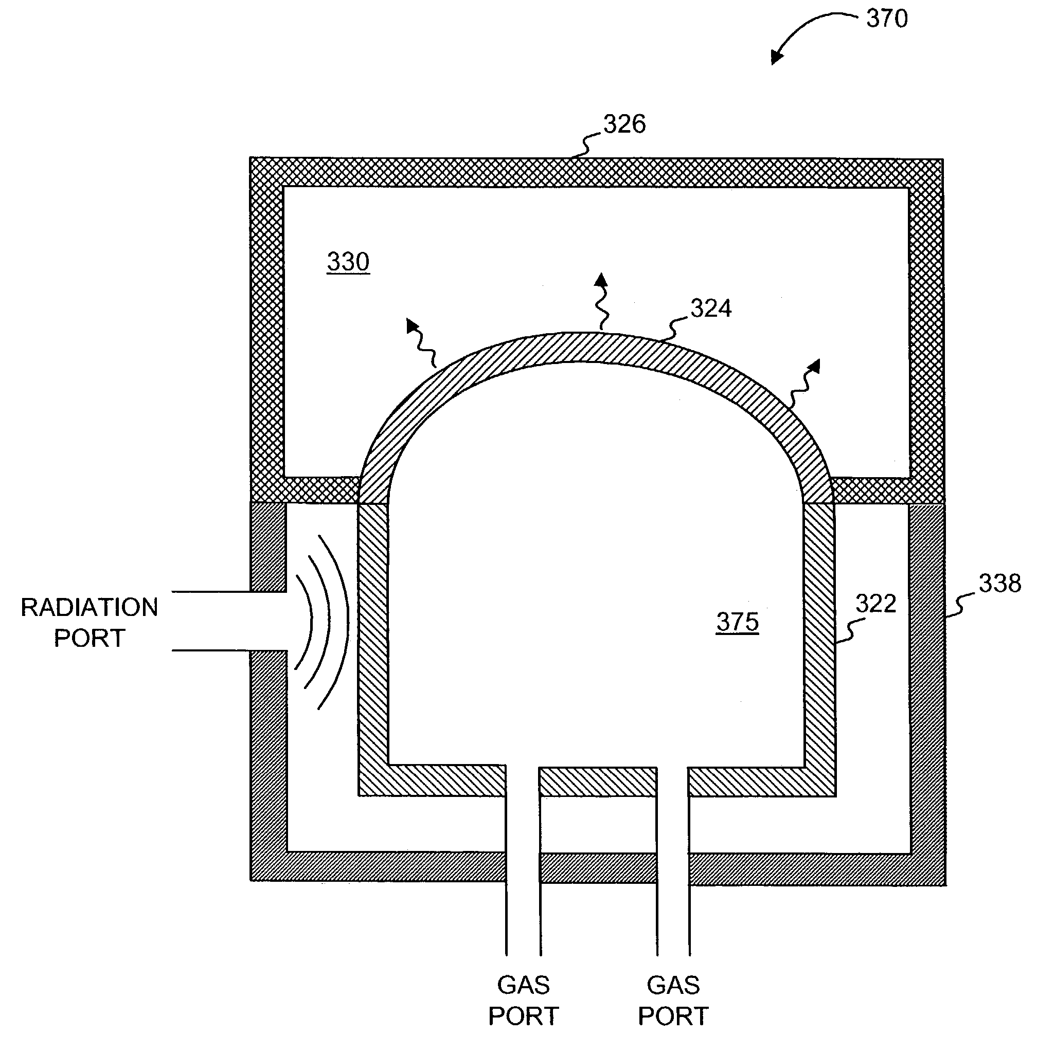
[0033]Consistent with the present invention, systems and methods for plasma-assisted heating and melting are provided. As described more fully below, any type of matter (e.g., solid, fluid, or gas) can be heated by modulating or sustaining a plasma in a cavity, optionally with a plasma catalyst. In one embodiment, the cavity may have a radiation-transmissive wall and a thermally conductive wall. A plasma can be formed in the cavity by irradiating a gas located in the cavity with electromagnetic radiation. As the temperature of the plasma rises, radiative energy absorbed by the plasma can be transferred, in the form of thermal energy, to the matter (in an adjacent chamber, for example) through the thermally conductive wall. In one embodiment, a radiation source, such as a microwave radiation source, may direct radiation at the gas.

[0034]It will be appreciated that multiple radiation sources may be used consistent with this invention, such as described in commonly owned U.S. patent ap...


PUM

PropertyMeasurementUnit
frequencyaaaaaaaaaa
temperaturesaaaaaaaaaa

Abstract

Apparatus and methods for plasma-assisted melting are provided. In one embodiment, a plasma-assisted melting method can include: (1) adding a solid to a melting region, (2) forming a plasma in a cavity by subjecting a gas to electromagnetic radiation having a frequency less than about 333 GHz in the presence of a plasma catalyst, wherein the cavity has a wall, (3) sustaining the plasma in the cavity such that energy from the plasma passes through the wall into the melting region and melts the solid into a liquid, and (4) collecting the liquid. Solids that can be melted consistent with this invention can include metals, such as metal ore and scrap metal. Various plasma catalysts are also provided.

Description

CROSS-REFERENCE OF RELATED APPLICATIONS[0001]This is a continuation-in-part of International Patent Application No. PCT / US03 / 14133, filed May 7, 2003, entitled “PLASMA HEATING APPARATUS AND METHODS” , and claims priority to U.S. Provisional Application Nos. 60 / 430,677, filed Dec. 4, 2002, 60 / 435,278, filed Dec. 23, 2002, all of which are fully incorporated herein by reference.FIELD OF THE INVENTION[0002]This invention relates to methods and apparatus for plasma-assisted heating and melting, and in particular to melting metals and other solid materials.BACKGROUND OF THE INVENTION[0003]Blast furnaces have been used to chemically reduce and physically convert iron oxides into liquid iron. Often, the blast furnace includes a large steel stack lined with refractory brick, where iron ore, coke, and limestone are dumped into the top, and preheated air is blown into the bottom. These materials descend to the bottom of the furnace where they become the final product of liquid slag and liquid...

Claims


Application Information

Patent Timeline
Patent Type & Authority Patents(United States)
IPC IPC(8): B23K10/00C12N15/55C21B13/12C21C5/52C22B4/00C22B4/08C22B9/22C23CF01N3/20F01N13/10H01J37/32H05B6/68H05B6/78H05B6/80H05H1/24H05H1/46
CPCC21B13/125C22B4/005C22B4/08C22B9/226F27D7/06F27D99/0006H01J37/32009H01J37/32192H01J37/32366H05B6/6402H05B6/78H05B6/784H05H1/24H05H1/46C21C5/5205Y10S588/90F27D2099/0026H01J2237/0206H01J2237/33H01J2237/336H01J2237/338H05H1/461Y02P10/20
Inventor KUMAR, SATYENDRAKUMAR, DEVENDRA
Owner BTU INTERNATIONAL
Why Eureka
Try Eureka