
Apparatus, method, program and recording medium for image restoration

a technology of image restoration and apparatus, applied in the field of image restoration apparatus, image restoration method, program and recording medium, can solve the problems of degrading the actual obtained image, affecting the quality of the image, and not always affecting the entire image, so as to reduce the discontinuity on the border between the divisional areas, the effect of suppressing ringing and noise enhancemen

Inactive Publication Date: 2007-03-13
MINOLTA CO LTD
View PDF10 Cites 16 Cited by
  • Summary
  • Abstract
  • Description
  • Claims
  • Application Information

AI Technical Summary

Benefits of technology

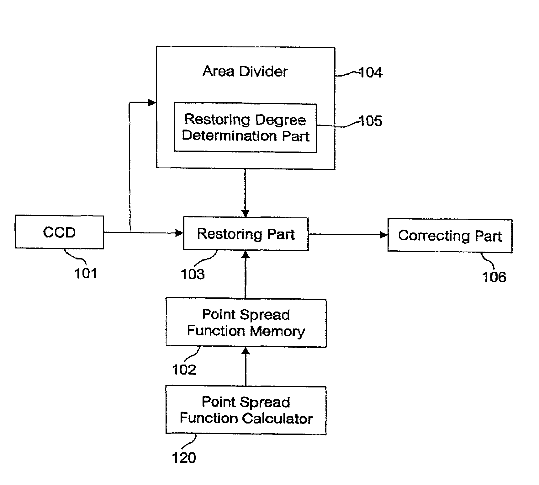
[0013]According to this image restoration apparatus, the restoration degree is determined for each of portions of the image, and each of the portions of the image is restored in accordance with the determined restoration degree. Consequently, not only ringing and noise enhancement which are caused when restoration is performed on areas not requiring restoration are effectively suppressed but also the border between the divisional areas is less conspicuous than when the image is divided into two kinds of areas, namely, an area on which restoration is performed and an area on which no restoration is performed. As a result, a restored image being natural as a while can be obtained.
[0015]According to this image restoration method, not only ringing and noise enhancement are effectively suppressed but also discontinuity on the border between the divisional areas is reduced unlike when the image is divided into two kinds of areas, so that a natural restored image can be obtained.

Problems solved by technology

Image degradation is that the actually obtained image is degraded compared to the ideal image to be obtained from the object to be taken.
The image is also degraded by a camera-shake caused at the time of photo-taking.
However, image degradation is not always caused on the entire image.
When image restoration is performed on the entire image, there are cases where an area not requiring restoration is also adversely affected.
For example, when restoration is performed on an area where noise and an edge are present, ringing and noise enhancement are caused, so that the area not requiring restoration is also adversely affected.
However, according to this technique, since the area is divided into two kinds of areas, namely, an area to be restored and an area not to be restored, discontinuity on the border between the two kinds of areas is conspicuous, so that the restored image is unnatural.

Method used


Image

  • Apparatus, method, program and recording medium for image restoration
  • Apparatus, method, program and recording medium for image restoration
  • Apparatus, method, program and recording medium for image restoration

Examples


first embodiment

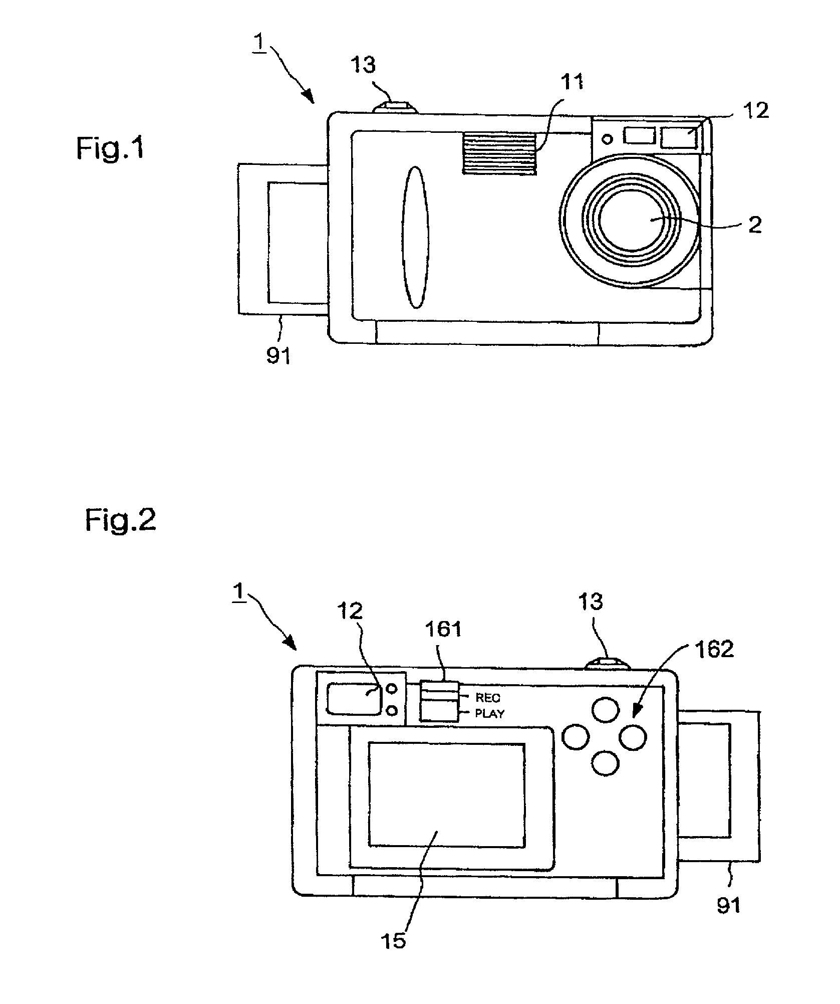
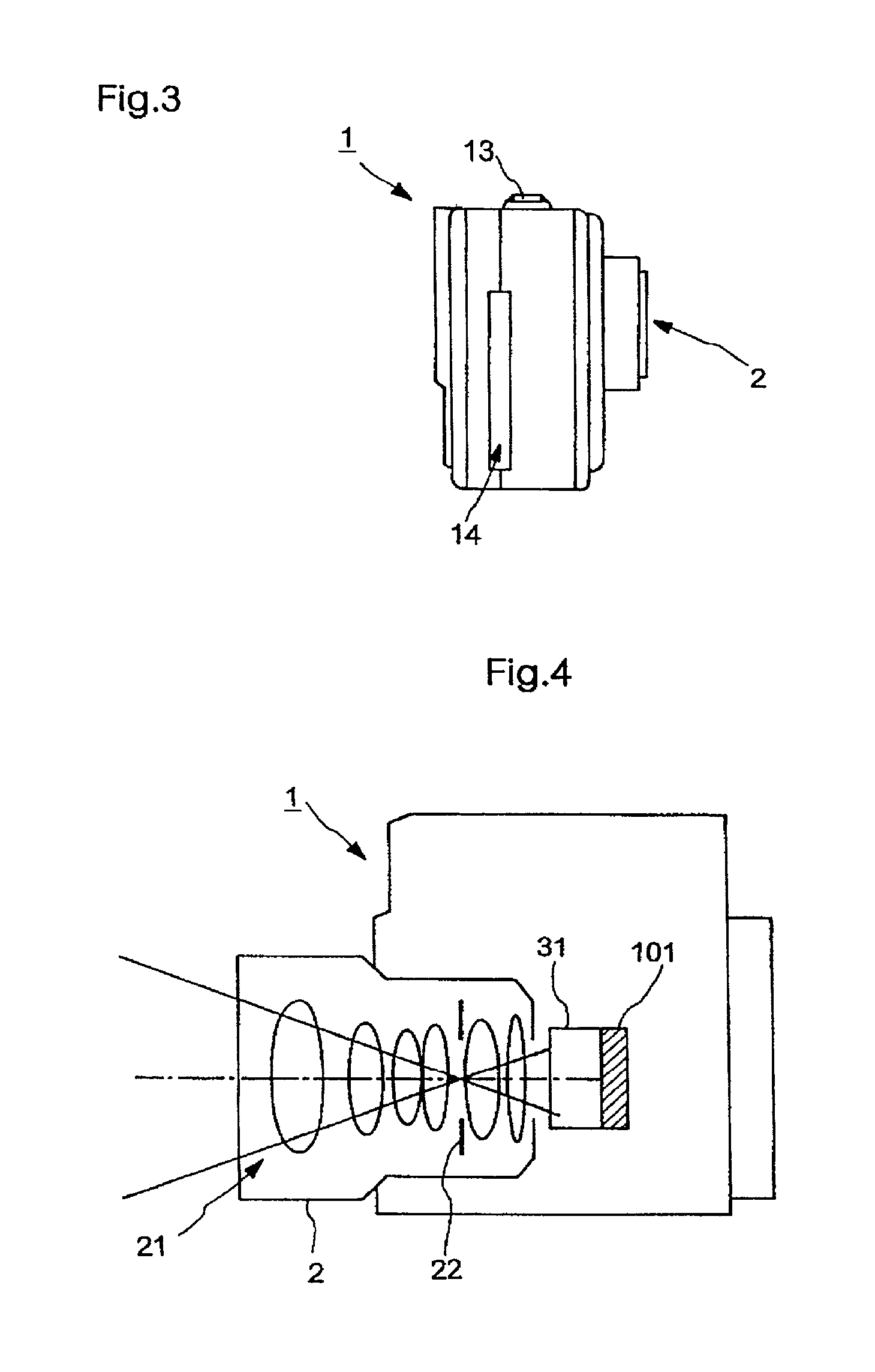
[0040]FIGS. 1 to 4 show the present invention. These figures show the appearance of a digital camera 1 as an image restoration apparatus. FIGS. 1 and 2 show a condition where a memory card 91 is under insertion or removal. The memory card 91 is not shown in FIG. 3.

[0041]The external structure of the digital camera 1 is similar to that of normal digital cameras. As shown in FIG. 1, on the front surface, a lens unit 2 directing light from the object to the CCD and an electronic flash 11 emitting flash light toward the object are disposed. Above the lens unit 2, a viewfinder 12 for viewing the area to be photographed of the object is disposed.

[0042]On the top surface, a shutter start button 13 (hereinafter, referred to as start button) for starting photo-taking is disposed. On the left side surface, as shown in FIG. 3, a card slot 14 for inserting the memory card 91 is provided.

[0043]On the rear surface of the digital camera 1, as shown in FIG. 2, the following are disposed: a liquid c...

second embodiment

[0101]Next, the present invention will be described.

[0102]When an area to be restored is determined by use of the contrast of the obtained image Y, the contrast is low in a completely blackened area, and this area is not included in the area to be restored. That is, the point spread function has a characteristic that eliminates or reduces a specific frequency component, and for example, there are cases where the contrast of a striped area in the original (ideal image) becomes substantially zero in the obtained image Y.

[0103]An apparatus and a method modifying, to solve this problem, image division based on the contrast of the obtained image (degraded image) and the contrast of the restored image will be described with reference to FIGS. 17 and 18.

[0104]FIG. 17 is a block diagram showing the structure of a function associated with photo-taking of the digital camera 1. The same parts as those of FIG. 12 are designated by the same reference numbers and description thereof is omitted.

[0...

third embodiment

[0116]Next, the present invention will be described.

[0117]Normally, random noise is superimposed on the obtained image and the point spread function, and there are cases where the noise is enhanced in the restored image. An apparatus and a method composing a plurality of restored images restored by use of different restoration degree weighting matrices to solve this problem will be described with reference to FIGS. 19 and 20.

[0118]FIG. 19 is a block diagram showing the structure of a function associated with photo-taking of the digital camera 1. The same parts as those of FIG. 17 are designated by the same reference numbers and description thereof is omitted.

[0119]In FIG. 19, the digital camera 1 has a composer 109 as well as the first and the second area dividers 104A and 104B and the first and the second restoration degree determiners 105A and 105B, and the restorer 103 has a first restorer 103A, a second restorer 103B and a storage 103C.

[0120]The first restorer 103A restores the ...


PUM


Abstract

An image of which restoration degree is determined based on the difference between each pixel and a neighboring pixel of the pixel in a light receiving element array 101 is divided into a plurality of areas based on the determined restoration degree, and the areas of the image are each restored in accordance with the determined restoration degree. By doing this, not only ringing and noise enhancement can effectively be suppressed but also the border between the areas which is conspicuous when the image is divided into two kinds of areas becomes less conspicuous, so that a natural restored image can be obtained.

Description

[0001]This application is based on application No. 2001-100478 filed in Japan, the content of which is hereby incorporated by reference.BACKGROUND OF THE INVENTION[0002]1. Field of the Invention[0003]The present invention relates to an image restoration apparatus, an image restoration method, a program and a recording medium for restoring the degradation of an image obtained as image data by a digital camera or the like.[0004]2. Description of the Related Art[0005]Conventionally, various techniques have been proposed to restore the degradation of an image obtained as image data by use of a light receiving element array such as CCD. Image degradation is that the actually obtained image is degraded compared to the ideal image to be obtained from the object to be taken. For example, an image obtained by use of a digital camera is degraded by aberrations depending on, e.g. the aperture value, the focal length and the position of focus point, and is further degraded by an optical low pas...

Claims


Application Information

Patent Timeline
IPC IPC(8): G03B13/00H04N5/217H04N5/232H04N5/225G06T5/20G06T5/00H04N1/40H04N1/409H04N101/00
CPCH04N1/4092G06T5/20G06T5/003G06T2207/20012G06T5/73
Inventor NAKANO, YUUSUKEYAMANAKA, MUTSUHIROSATO, KAZUCHIKA
Owner MINOLTA CO LTD
Learn More