Magnetic recorder having carbon nanotubes embedded in anodic alumina for emitting electron beams to perform heat-assisted magnetic recording

a carbon nanotube and electron beam technology, applied in the field of heat-assisted magnetic recorders, can solve the problems of not being able to maintain the domain, unreasonable to expect a further improvement in the magnetic recording field, and becoming increasingly difficult to meet the demands for the increase in recording density

Active Publication Date: 2007-03-13
ORACLE INT CORP
View PDF15 Cites 20 Cited by
  • Summary
  • Abstract
  • Description
  • Claims
  • Application Information

AI Technical Summary

Problems solved by technology

However, if the volume of the magnetization reversal unit is diminished, then the magnetic anisotropy energy of the unit (Ku (density of magnetic anisotropy energy) * V (volume of the magnetization reversal unit)) becomes smaller than the thermal fluctuation energy, and it will be no longer possible to maintain the domains.
In this connection, it is noted that magnetic recording head characteristics which determine the magnetic recording field are rapidly reaching their physical limit, making it unreasonable to expect a further improvement in the magnetic recording field.
That is, it is becoming increasingly difficult to comply with the demands for the increased recording density by simply increasing Ku.
Accordingly, recording onto a medium at room temperature and a large Ku value is not possible because the magnetic field intensity necessary for recording exceeds the intensity of a magnetic recording field generated by a magnetic head.
The problem with using a laser beam generator to locally heat a medium is that it is difficult to efficiently deliver laser beam power to a relatively small area of the medium.
As a result, a diffraction limited laser beam undesirably heats adjacent tracks of the medium.
The subsequent heating of the head can be problematic for actual devices.

Method used


Image

  • Magnetic recorder having carbon nanotubes embedded in anodic alumina for emitting electron beams to perform heat-assisted magnetic recording
  • Magnetic recorder having carbon nanotubes embedded in anodic alumina for emitting electron beams to perform heat-assisted magnetic recording
  • Magnetic recorder having carbon nanotubes embedded in anodic alumina for emitting electron beams to perform heat-assisted magnetic recording

Examples


Embodiment Construction

)

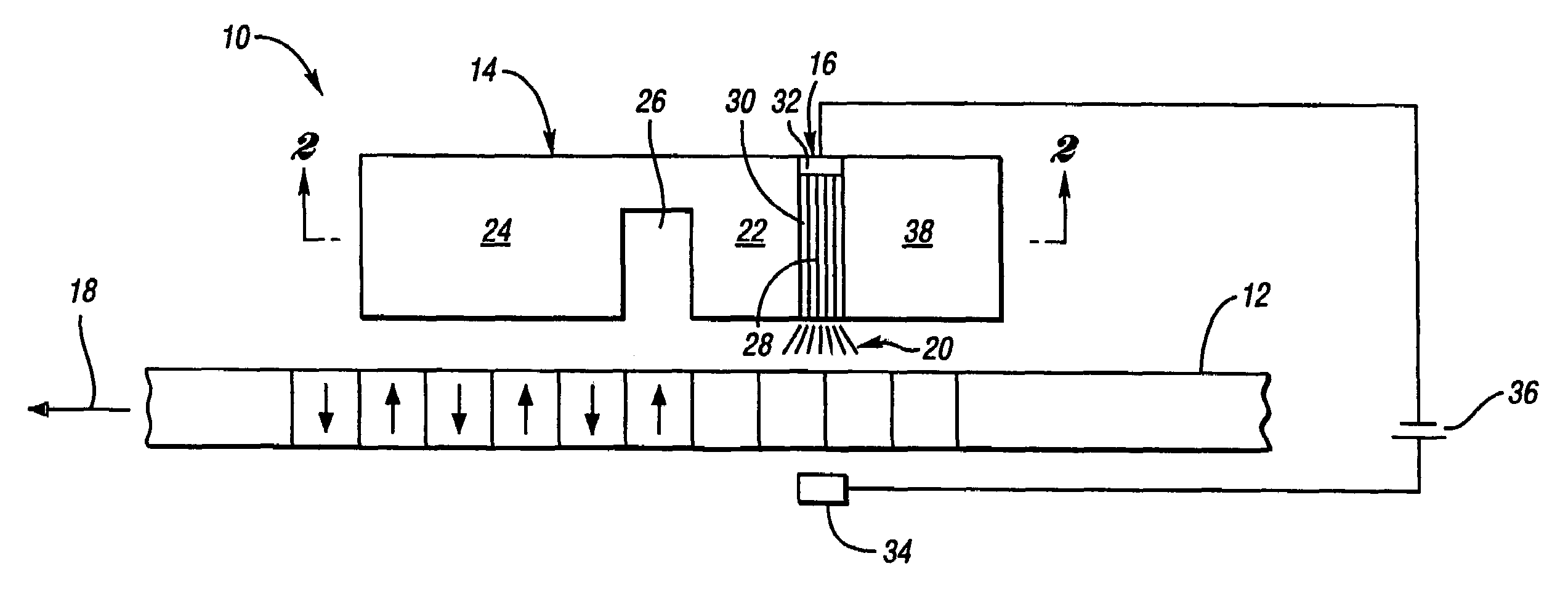
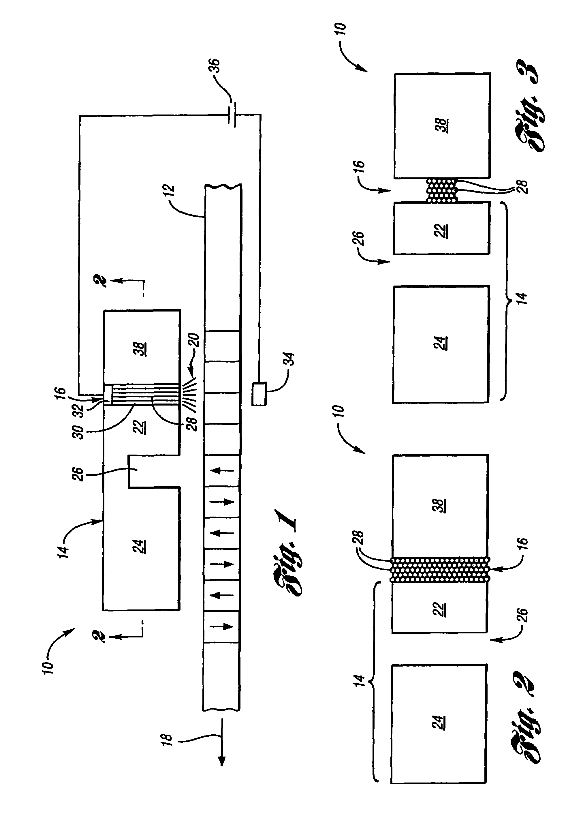
[0030]Referring now to FIG. 1, a cross-sectional view of a heat-assisted magnetic recorder 10 (i.e., a thermally-assisted magnetic recorder 10) in accordance with an embodiment of the present invention is shown. Magnetic recorder 10 is used for magnetically recording information to a magnetic recording medium such as a magnetic disk 12. Magnetic recorder 10 generally includes a magnetic recording head 14 and an electron beam generator 16 (i.e., electron bean emitter 16). Recording head 14 and electron beam generator 16 function together to perform heat-assisted magnetic recording of information onto disk 12.

[0031]Magnetic recorder 10 is spaced relatively close to disk 12 (on the order of 100 nm or less) in order to magnetically record information onto the disk. Magnetic recorder 10 magnetically records information onto disk 12 as the disk moves relative to the magnetic recorder in the direction indicated by arrow 18. The relative movement between magnetic recorder 10 and disk 12 is...


PUM

PropertyMeasurementUnit
sizesaaaaaaaaaa
currentaaaaaaaaaa
energyaaaaaaaaaa

Abstract

A heat-assisted magnetic recorder for magnetically recording information onto a recording medium having a given recording coercive field includes an electron beam generator and a magnetic recording head. The electron beam generator directs an electron beam onto the recording medium in order to locally heat a portion of the recording medium such that the heated recording medium portion has a recording coercive field lower than the given recording coercive field. The magnetic recording head generates a magnetic recording field having an intensity greater than the recording coercive field of the heated recording medium portion in order to magnetically record information onto the heated recording medium portion. The electron beam generator includes a plurality of carbon nanotubes (CNTs) embedded in nanoholes of an anodic alumina template for generating the electron beam. A heat-assisted magnetic recording method is associated with the heat-assisted magnetic recorder.

Description

BACKGROUND OF THE INVENTION[0001]1. Field of the Invention[0002]The present invention generally relates to heat-assisted magnetic recorders and, more particularly, to a magnetic recorder having carbon nanotubes (CNTs) embedded in an anodic alumina template for emitting electron beams onto a magnetic recording medium in order to perform heat-assisted magnetic recording of the medium.[0003]2. Background Art[0004]Magnetic recording mediums for recording information have a magnetic layer comprised of minute magnetic grains. Magnetic domains recorded on the magnetic layer have to be small enough to accommodate high-density recording carried out by a magnetic recording head. In order to enable clear distinction of small recording magnetic domains, the boundaries of the domains should be smooth enough, and this results in the reduction of the grain size. The propagation of magnetization reversal among the grains distorts the domain boundary. Thus, individual grains can be isolated magnetic...

Claims


Application Information

Patent Timeline
Patent Type & Authority Patents(United States)
IPC IPC(8): G11B5/02
CPCB82Y10/00B82Y25/00G11B5/1278G11B5/02G11B2005/0021G11B2005/0005
Inventor NIBARGER, JOHN P.
Owner ORACLE INT CORP
Why Eureka
Try Eureka