Electronic control enclosure

a technology of electronic control and enclosure, which is applied in the direction of electrical apparatus casing/cabinet/drawer, power cables, insulated conductors, etc., can solve the problems of damage to electronic components and measures to be taken, and achieve the effect of improving heat energy transfer and removing heat energy generated

Active Publication Date: 2007-03-13
CINCH CONNECTORS
View PDF53 Cites 37 Cited by
  • Summary
  • Abstract
  • Description
  • Claims
  • Application Information

AI Technical Summary

Benefits of technology

[0007]An advantage of the invention is that it provides an electronic control enclosure for protectively enclosing the electronic components of an electronic control unit. Another advantage is that the invention removes heat energy generated by the electronic components and transfers that heat energy to the exterior of the electronic control enclosure. Another advantage is that the invention is configured to improve the transfer of heat energy between an exposed heat transfer surface of the electronic components and a heat sink. These and other advantages and features of the invention will become apparent from the foregoing detailed description and drawings.
is that it provides an electronic control enclosure for protectively enclosing the electronic components of an electronic control unit. Another advantage is that the invention removes heat energy generated by the electronic components and transfers that heat energy to the exterior of the electronic control enclosure. Another advantage is that the invention is configured to improve the transfer of heat energy between an exposed heat transfer surface of the electronic components and a heat sink. These and other advantages and features of the invention will become apparent from the foregoing detailed description and drawings.

Problems solved by technology

Such applications may expose the electronic control unit to airborne dirt and grime that, if allowed to enter the enclosure housing, could damage the electronic components.
However, because the electronic components located in the enclosure housing typically generate heat energy during operation that could potentially damage the components, measures must be taken to cool the components.

Method used


Image

  • Electronic control enclosure
  • Electronic control enclosure
  • Electronic control enclosure

Examples


Embodiment Construction

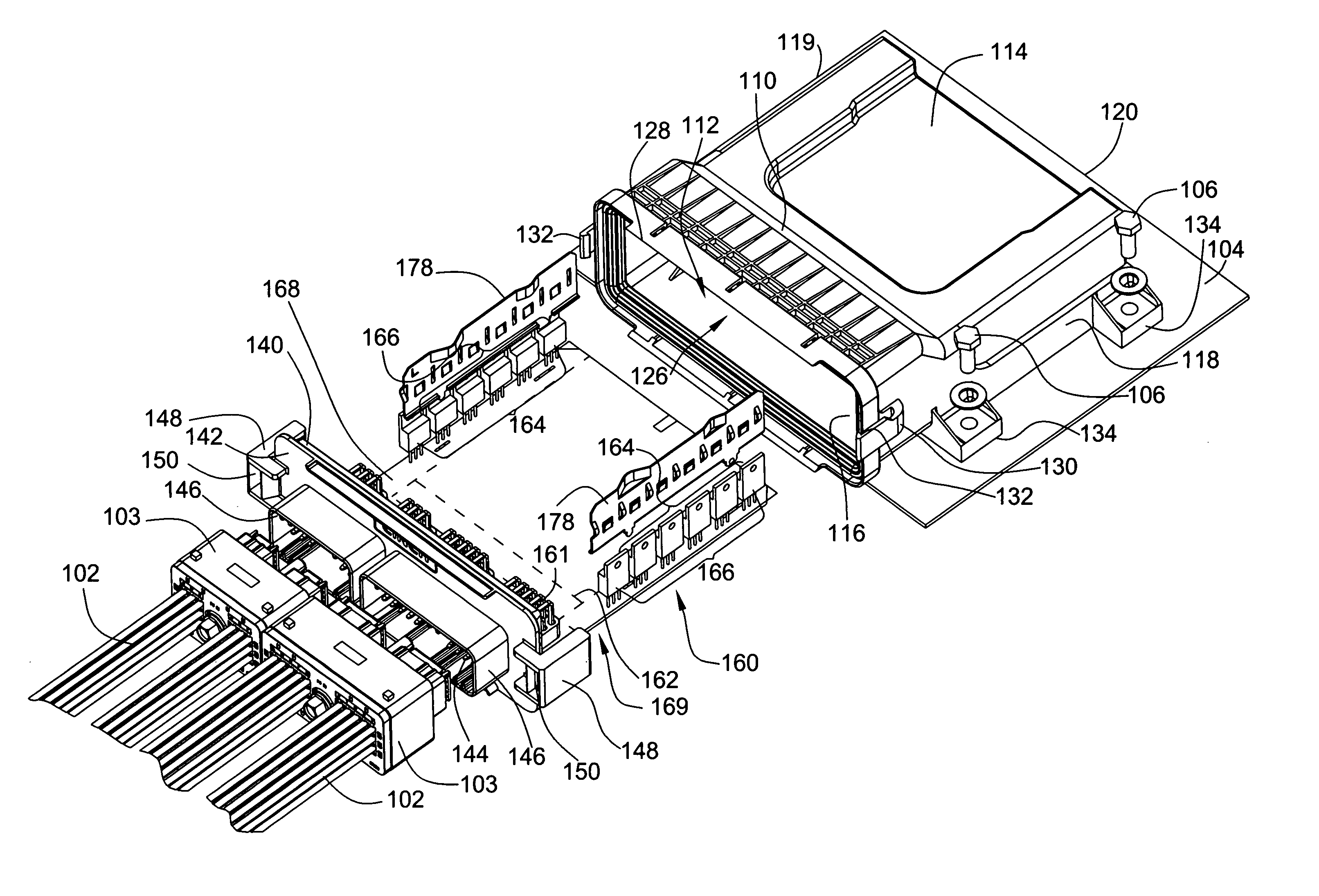
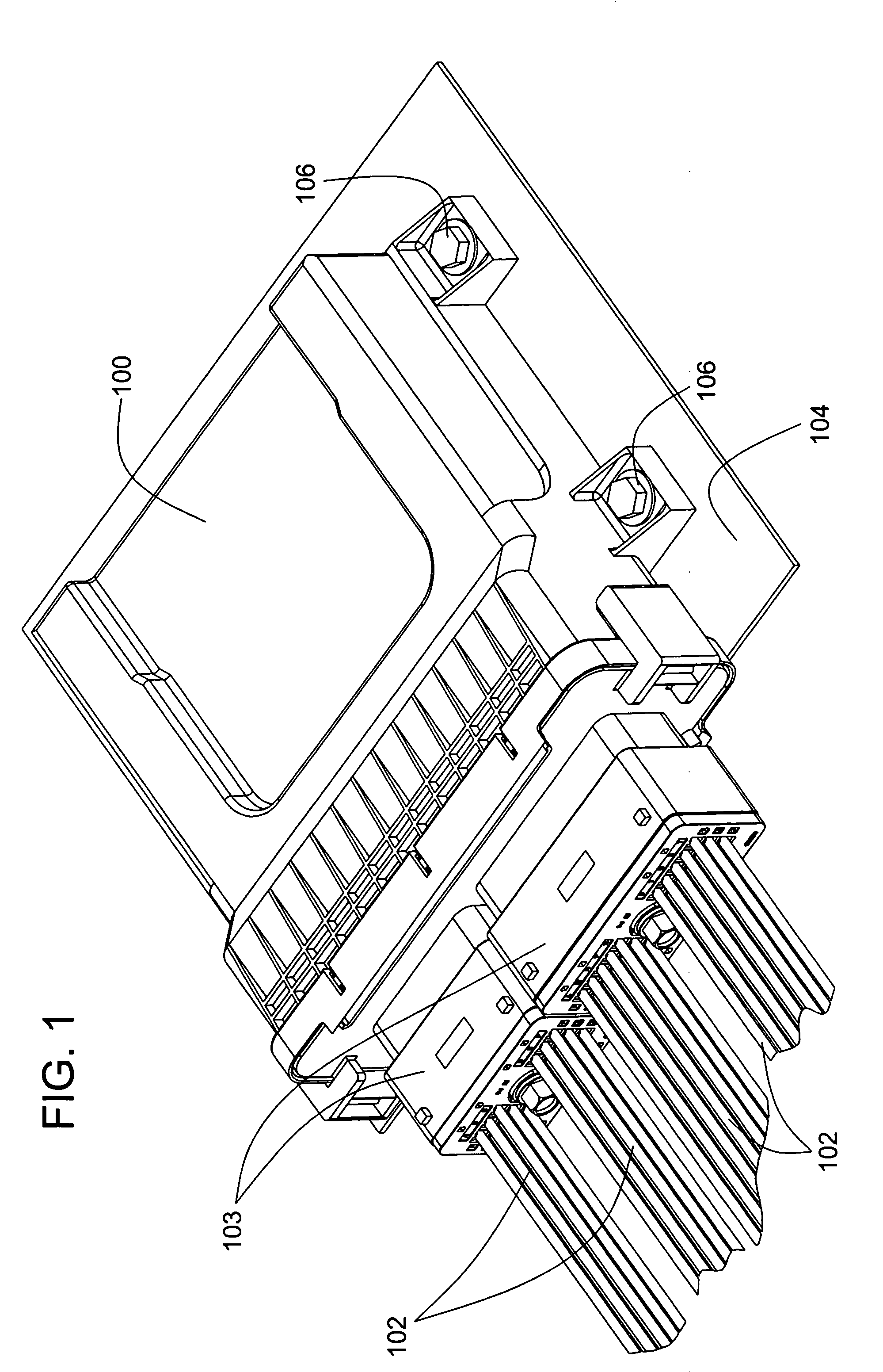
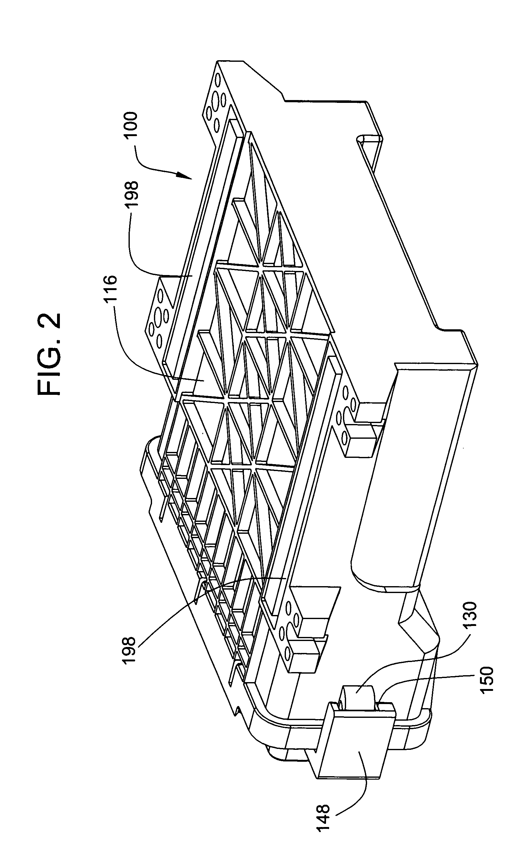
[0038]Now referring to the drawings, wherein like reference numbers refer to like elements, there is illustrated in FIGS. 1, 2 and 3 the exterior of an embodiment of an electronic control enclosure 100 for an electronic control unit designed in accordance with the teachings of the invention. The electronic control unit can be used to control externally situated electrical devices. The electrical elements and components making up the electronic control unit are located in the interior of the electronic control enclosure 100, where they are protected from the exterior environment. To establish communication between the internal elements and components and the externally situated electrical devices, one or more electrical cables 102 that terminate in plugs 103 are plugged into the electronic control enclosure 100.

[0039]The electronic control enclosure 100 can be secured to a panel 104 situated proximate to the external electrical devices with one or more fasteners 106, though, in other...


PUM


Abstract

The electronic control enclosure includes devices and methods for removing heat energy from the electronic components of an electronic control unit. The components are mounted to a substrate and are protectively housed in an interior chamber of an environmentally sealed enclosure housing. Electrical communication is established with the components via a header assembly that includes plug receptacles. To remove heat generated by the components from the enclosure housing, one or more heat sinks are disposed through the enclosure housing such that the heat sinks have an interior surface exposed to the interior chamber and an exterior surface exposed to the exterior of the enclosure housing. In other embodiments, the enclosure housing may be made of a heat conductive material and the heat sink is integral with the enclosure housing. In one aspect, a spring urges the components against the interior surface. In another aspect, the components are mounted to and directly contact the interior surface.

Description

FIELD OF THE INVENTION[0001]This invention pertains generally to electronic control units and more particularly to an electronic control enclosure for housing the electronic components of an electronic control unit and that is configured to dissipate heat from within the enclosure.BACKGROUND OF THE INVENTION[0002]Electronic control units are typically used in various applications to control electronic or electrical devices and, accordingly, are made of many electronic components. Often, the electronic components are mounted to a printed circuit board to both establish electrical communication between the components and to keep the components in a tightly grouped assembly. To protect the electronic components from damage due to impact with external objects and to simplify distribution and attachment of the electronic control unit, the components are also often housed in a protective enclosure housing.[0003]In some applications, the electronic control unit is required to be placed in ...

Claims


Application Information

Patent Timeline
Patent Type & Authority Patents(United States)
IPC IPC(8): H05K7/20
CPCH05K5/061H05K5/0039H05K7/20854H05K7/2049
Inventor CAINES, ARTUROKOSTIC, BRATISLAVRACHWALSKI, THADDEUS
Owner CINCH CONNECTORS
Why Eureka
Try Eureka