Access port indicator for implantable medical device

a technology access ports, which is applied in the field of access port indicators for implantable medical devices, can solve the problems of increasing the risk of infection, and affecting the patient's recovery,

Inactive Publication Date: 2007-03-13
ADVANCED NEUROMODULATION SYST INC
View PDF10 Cites 93 Cited by
  • Summary
  • Abstract
  • Description
  • Claims
  • Application Information

AI Technical Summary

Benefits of technology

[0006]Aspects of the invention are found in an implantable medical device. The implantable medical device such as an implantable drug pump has a port for injecting fluid and a set of energy emitters indicating the location of the port. The device can also have a circuitry coupled to the one or more energy emitters. The energy emitters can be light emitting diodes, edge emitting diodes, or VCSELs, sonic emitters, among emitters. The implantable device can also have a second port and a second set of energy emitters associated with the second port. The second set of energy emitters can emit energy different from that of the first set of the electromagnetic energy emitters. For example, the two sets can display differing colors. The sets of energy emitters can be arranged around the ports in various shapes such as triangles, squares, circles, among others. The ports can be used for bolus injections or refill of reservoirs.

Problems solved by technology

However, many problems arise in locating the access port and accurately inserting the needle.
If the needle is inserted in the skin at a location relatively far from the access port, the patient can experience additional pain and tissue damage.
This tissue damage can be caused by attempting to stretch the tissue and skin to move the needle into position.
This repeated sticking and / or jogging of the needle ultimately causes pain, discomfort and tissue damage to the patient.
In addition, attempts to stick the syringe or needle into the access port can cause damage to the needle tip.
This damage can scar or core the access port when the needle is inserted or withdrawn, causing a channel or tunnel to be created in the access port.
The channel or tunnel can ultimately lead to leaking of pharmaceutical solutions.
As such, typical port access systems suffer from deficiencies in indicating a location of the port and allowing easy and accurate access to the port.

Method used


Image

  • Access port indicator for implantable medical device
  • Access port indicator for implantable medical device
  • Access port indicator for implantable medical device

Examples


Embodiment Construction

[0017]Implantable medical devices such as drug infusion pumps are used in various applications to treat various conditions including pain, muscular disorders, and cancer, among others. Periodically, the pumps require refilling. In addition, some pumps permit bolus injections to be administered through an access port. However, problems often arise in locating the ports of medical devices and delivery of materials such as accurately sticking a syringe into the ports.

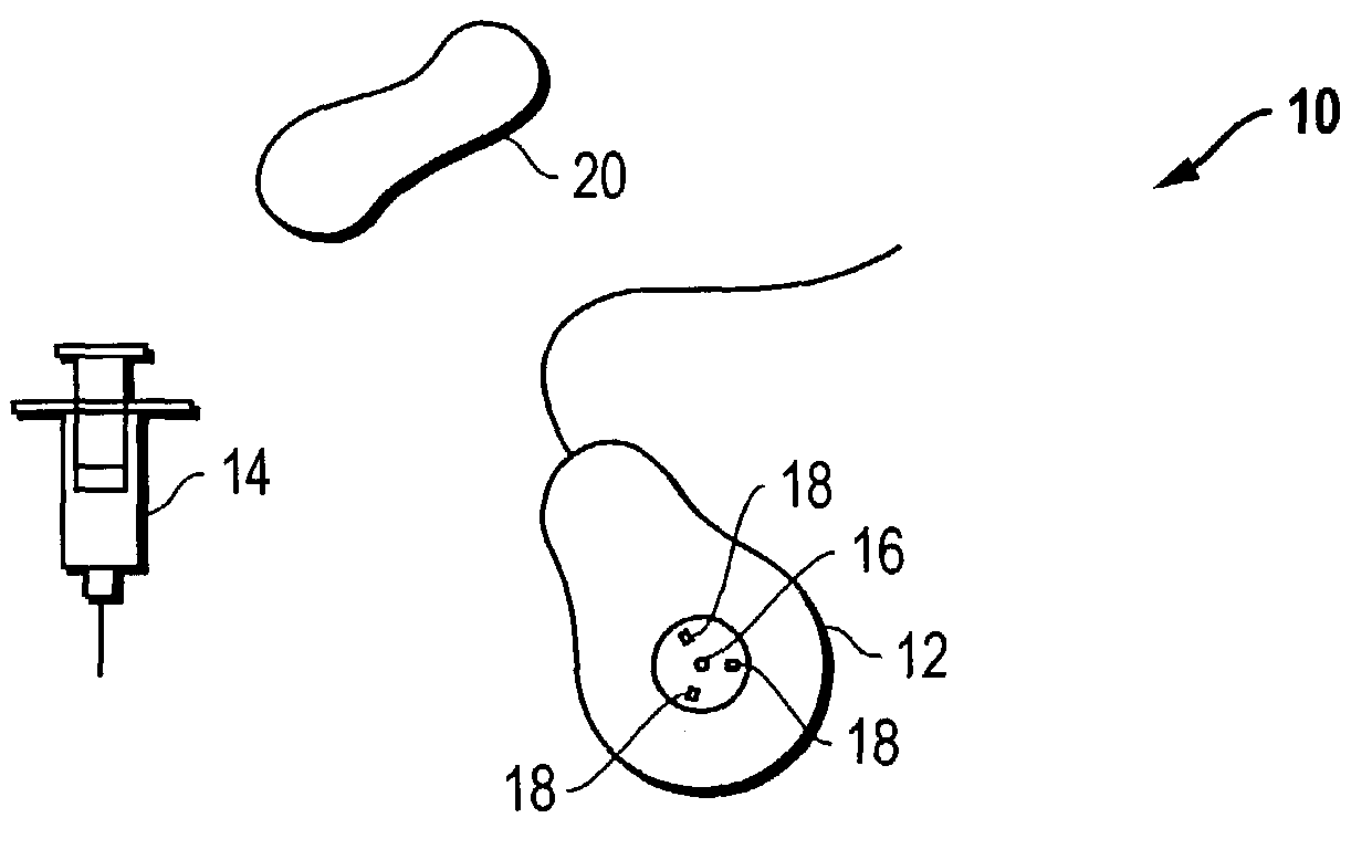
[0018]The present invention is directed to a system and method for indicating the location of a port on an implantable medical device, such as a drug infusion pump. FIG. 1 depicts an exemplary system 10 including an implantable pump 12, a syringe 14 and an activation device 20. The implantable pump 12 can have a port 16. The port 16 can permit bolus injections or be useful in refilling a reservoir.

[0019]Arranged in proximity to the port can be one or more emitters 18. Emitters 18 can, for example, emit a visible wavelength...


PUM


Abstract

The invention is directed to an implantable pump. The implantable pump has a port with light emitters indicating the location of the port. The port can be useful in providing bolus injections or the refilling of reservoirs. The light emitters can be arranged in various forms about the port including linear, triangular, square, or circular, among others. If more than one port is located on a device, these ports can be differentiated by differing colors and arrangements of emitters. In addition, various circuitries can be used to activate the emitters. These circuitries can include a coil and capacitor arrangement that provide a separate power source from that of the pump.

Description

BACKGROUND OF THE INVENTION[0001]Medical devices such as drug infusion pumps are used to treat various ailments and conditions through the delivery of pain medication, anti-spasmatic agents, chemotherapeutic agents, and other pharmaceutical agents. In treating these ailments, the drug infusion pumps can periodically require refilling through a fill access port. In addition, access ports can be provided for bolus injections.[0002]Typically, these devices are placed in fatty tissue under the skin. Access to the ports often is obtained by piercing the skin with a needle or syringe and guiding the syringe through the access port. However, many problems arise in locating the access port and accurately inserting the needle.[0003]If the needle is inserted in the skin at a location relatively far from the access port, the patient can experience additional pain and tissue damage. This tissue damage can be caused by attempting to stretch the tissue and skin to move the needle into position. A...

Claims


Application Information

Patent Timeline
Patent Type & Authority Patents(United States)
IPC IPC(8): A61N1/00A61M5/142A61M5/42A61M39/02
CPCA61M5/14276A61B2019/5255A61M2205/6081A61M39/0208A61M5/427A61B2034/2055
Inventor CANTLON, KURT
Owner ADVANCED NEUROMODULATION SYST INC
Why Eureka
Try Eureka