
Error correction in a locating method and system

a technology of error correction and locating method, applied in the field of communication, can solve problems such as computationally intensive processing techniques

Inactive Publication Date: 2007-03-13
LOCUS LOCATION SYST
View PDF26 Cites 13 Cited by
  • Summary
  • Abstract
  • Description
  • Claims
  • Application Information

AI Technical Summary

Benefits of technology

This approach allows for efficient and accurate determination of the transmitter's location using hyperbolic trilateration, minimizing data transmission and processing needs, and providing a bandwidth-efficient solution for locating transmitters in communication systems.

Problems solved by technology

However, such techniques require that the transmitter radiate an additional signal comprising the required locating information, or that a complex, computationally intensive processing technique be used to recognize a common characteristic of a randomly modulated signal to identify a time delay of arrival.

Method used


Image

  • Error correction in a locating method and system
  • Error correction in a locating method and system
  • Error correction in a locating method and system

Examples


Embodiment Construction

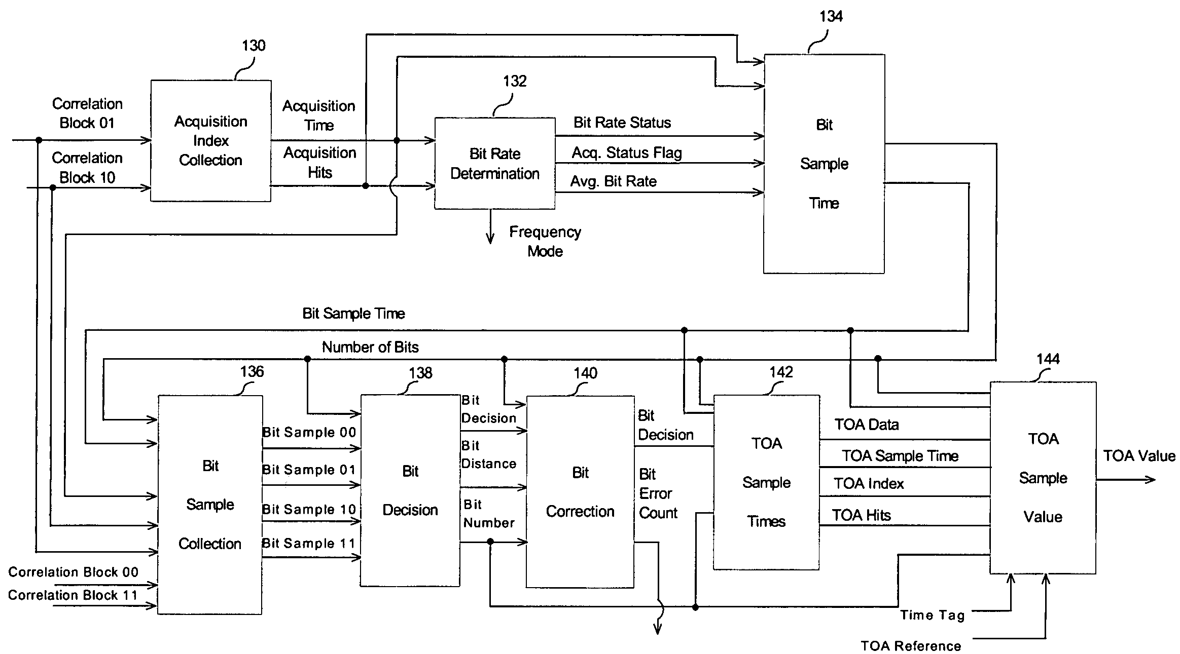
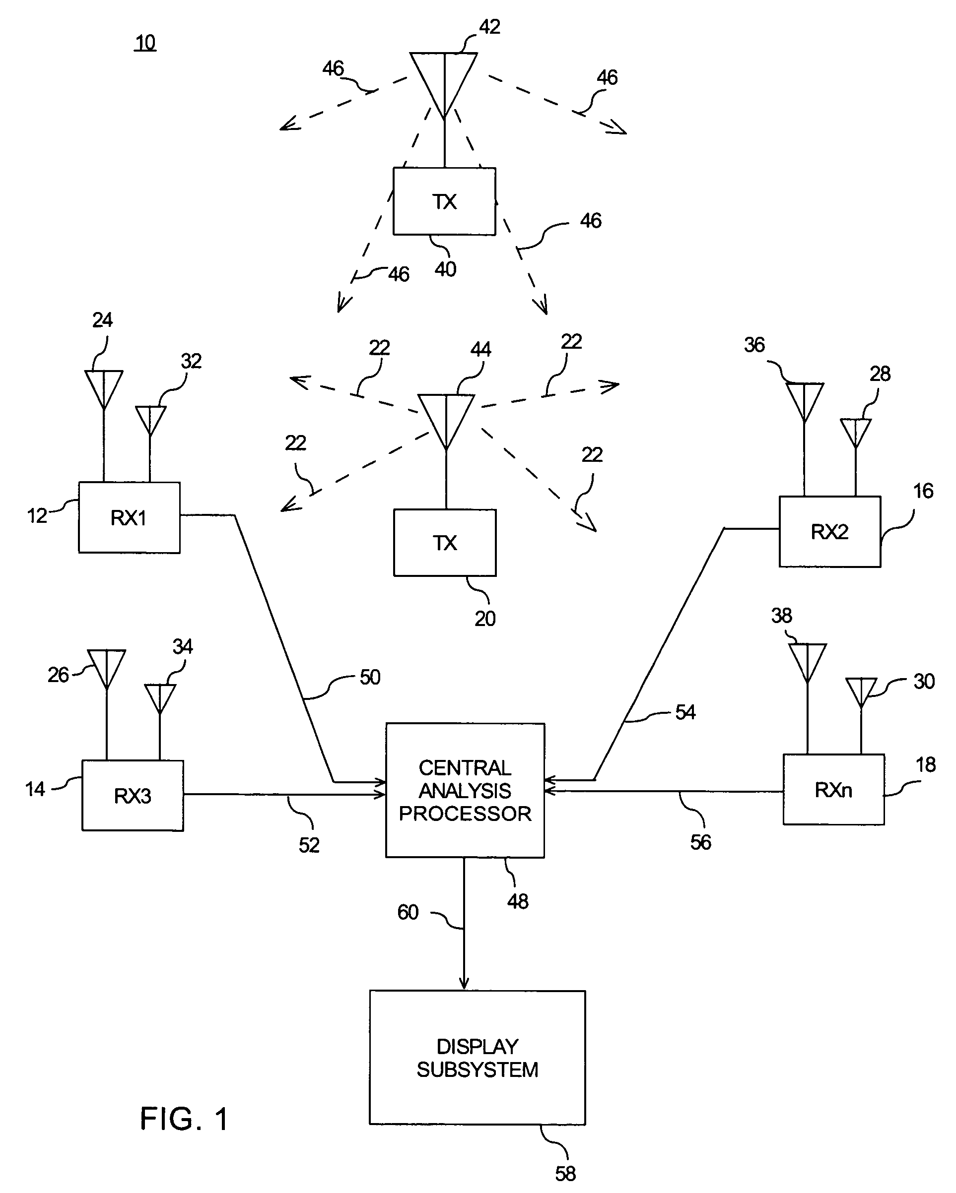
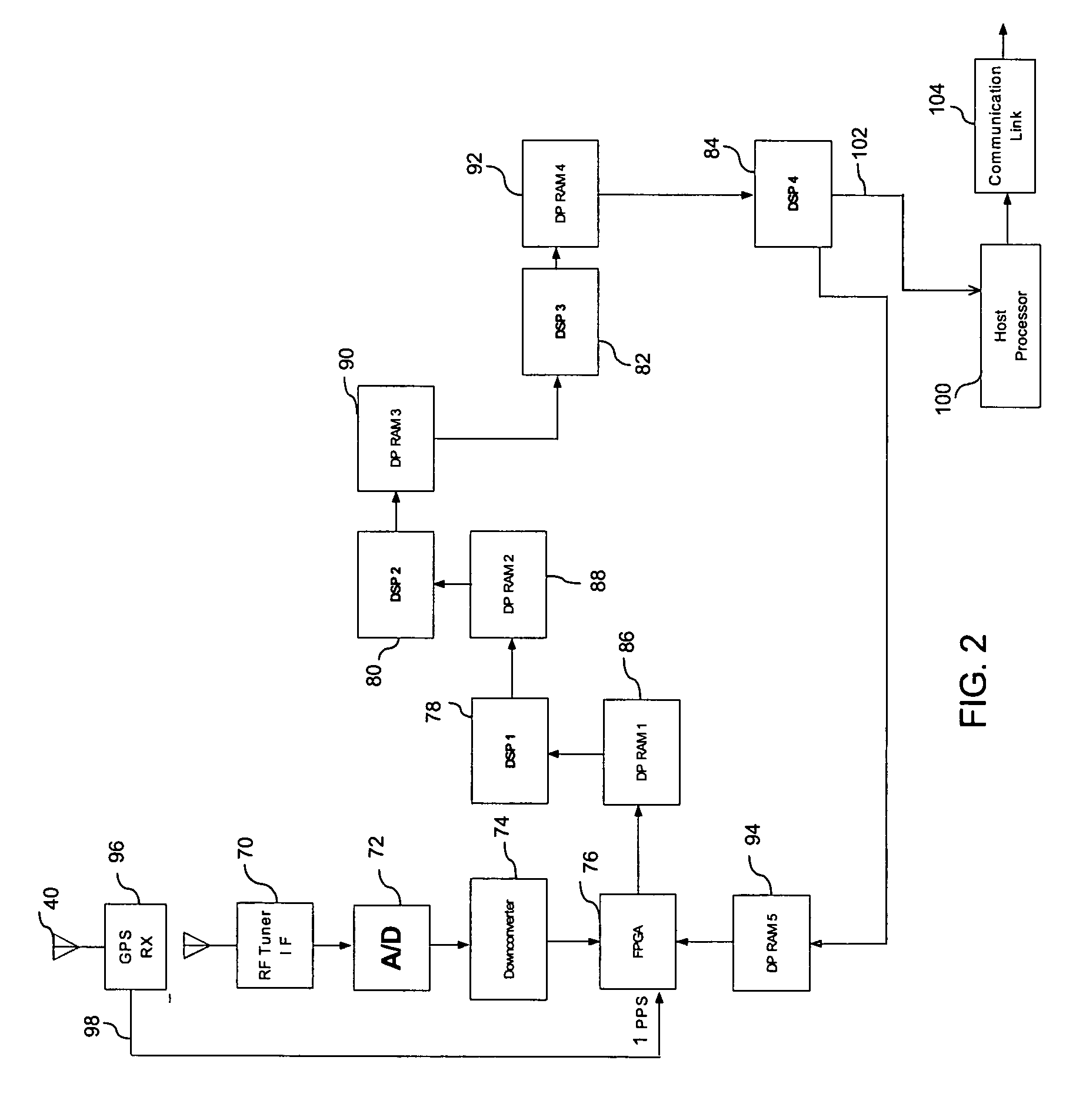
[0009]The inventors of the present invention have innovatively realized that by detecting information encoded in a transmitted digital signal, such as an Enhanced Digital Access Communications System (EDACS®), a SmartZone®, or a Project 25 formatted radio signal, the location of a transmitting unit may be quickly and efficiently determined based on time delay of arrival of a signal received at three or more spatially separated receivers. In an aspect of the invention, correlated bit transitions in a decoded digital data string are time stamped, and the resulting time stamps are compressed and provided to a central site. In another aspect of the invention, the respective times of arrivals for multiple bit transitions in the digital signal may be averaged to generate an average time of arrival for the entire decoded digital data string. The time stamp information from each of the receivers is used to determine a time delay of arrival of the signal at the spatially separated receivers....


PUM


Abstract

A method of detecting and correcting bit errors in a digitally encoded data stream includes correlating a received bit transition in the data stream with a multitude of possible bit transitions to generate corresponding correlated bit transition values. A bit transition decision corresponding to a greatest correlated bit transition value is then generated for the received bit transition. Consecutive bit transition decisions generated for the data stream are compared to identify bit transition decision errors. Respective bit transition decisions are examined to determine if each decision is consistent with a prior adjacent bit transition decision in the data stream. If a bit transition decision error is identified, then the next greatest correlated bit transition decision is substituted for the bit transition decision in error.

Description

SPECIFIC DATA RELATED TO INVENTION[0001]This application claims the benefit of U.S. Provisional Patent Application No. 60 / 465,103 filed Apr. 24, 2003.FIELD OF THE INVENTION[0002]This invention relates generally to the field of communications, and, in particular, to error correction in systems for locating a transmitting unit radiating a digitally encoded signal.BACKGROUND OF THE INVENTION[0003]It is known to determine the location of a transmitting unit based on time of arrival differences or phase differences of a signal radiated by the unit at spatially separated receivers. Proposed techniques have included detecting a phase difference at respective receivers of a steady tone radiated by the unit, detecting a time difference of arrival for clock synchronized pulses radiated by the unit, and detecting a time difference of arrival of a common reference level of a randomly modulated signal. However, such techniques require that the transmitter radiate an additional signal comprising ...

Claims


Application Information

Patent Timeline
Patent Type & Authority Patents(United States)
IPC IPC(8): H03M13/45G01S5/02G01S5/06G01S19/48H03M13/00H04Q1/00H04W64/00
CPCH04W64/00G01S5/06G01S5/0221G01S5/02216
Inventor OLAKER, DAVID A.
Owner LOCUS LOCATION SYST
Learn More