Deformable building sheet batten

a building sheet and batten technology, applied in the direction of roofs, ceilings, walls, etc., can solve the problems of inadequate waterproofing, damage to the sheet, misalignment of the cladding sheet, etc., and achieve the effect of preventing water ingress and facilitating drainag

Inactive Publication Date: 2007-03-20
JAMES HARDIE TECH LTD
View PDF19 Cites 51 Cited by
  • Summary
  • Abstract
  • Description
  • Claims
  • Application Information

AI Technical Summary

Benefits of technology

[0013]Preferably, the mounting flanges are formed with respective longitudinally extending recessed channels configured, in use, to provide a clearance space between the cladding sheets and the mounting flanges. By extending through this clearance space, the mounting screws are preferably disposed to accommodate a limited degree of pivotal movement, thereby permitting a limited degree of relative lateral displacement in two dimensions between the cladding sheet and the batten, in the plane of the sheet. The recessed channels advantageously also facilitate drainage and thereby help to prevent ingress of water in adverse weather conditions.

Problems solved by technology

Apart from the additional cost associated with such gaskets and backing strips, poor installation techniques may result in misalignment of the cladding sheets and damage to the sheets from over stressing along their edges, as well as inadequate waterproofing.
The process is also labour intensive.
If such fasteners are located even a few millimetres closer to the sheet edge or if the sheets are not fastened correctly, failure or “break out” of a sheet edge along the line of the fasteners can occur.
Lastly, in use it will be appreciated that stresses can be applied to the cladding sheet either internally or externally which can compromise the strength, weatherproofing or durability of conventional cladding systems.
In either case, such stresses can lead to premature wear, leakage, or even failure of various elements in the system.

Method used


Image

  • Deformable building sheet batten
  • Deformable building sheet batten
  • Deformable building sheet batten

Examples


Embodiment Construction

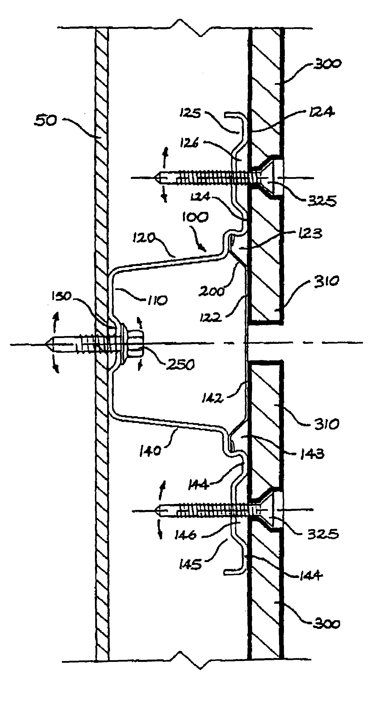
[0031]Referring firstly to FIG. 4, the batten 100 according to the present invention is comprised of a generally U-shaped channel member having arms or side walls 120 and 140 connected by an intermediate web 110.

[0032]The side walls diverge outwardly from the web, and terminate in corresponding flanges 125 and 145 extending laterally from their free edges. These flanges are adapted for connection to the cladding sheets as described below. In other embodiments, the side walls may be generally parallel, convergent, curved, V-shaped, omega (Ω) shaped, or be formed with any other suitable profile.

[0033]A detachable sealing strip 200, as shown in FIG. 5, is adapted to extend across and close the open section 160 of the channel, with longitudinal edges 165 captively and sealingly retained within respective mutually opposing groove 170. Appropriate installation of this weather sealing strip 200 is shown in FIG. 6.

[0034]FIG. 6 also shows the installation of the batten 100. The intermediate ...


PUM


Abstract

A batten (100) for mounting cladding sheets to a wall or frame, said batten comprising an elongate channel member having a pair of spaced apart side walls (120, 140) joined by an intermediate web (110), and a corresponding pair of mounting flanges (124, 145) spaced outwardly from the web (110) and extending laterally from the side walls (120, 140), adapted for connection to the cladding sheets (300), and the batten (100) being configured such that stress applied to the cladding sheets (300) in use results in preferential deformation of the batten.

Description

FIELD OF THE INVENTION[0001]The present invention relates to methods and apparatus for mounting cladding sheets over masonry or steel frame work. The invention has been developed primarily for use with fibre reinforced cement cladding sheets and will be described hereinafter with reference to this application. It will be appreciated, however, that the invention is also applicable to other cladding materials.BACKGROUND OF THE INVENTION[0002]Battens have previously been used by the applicant in their facade and fascia cladding systems. These battens are sometimes referred to as “top hats” due to their inverted U-shaped cross-section and outwardly splayed edge flanges. The function of these battens or top hats is to provide a planar fixing frame for connection of cladding sheets. As will be appreciated by those skilled in the art, when applying cladding sheets over an uneven surface it is important that the frame on which the cladding sheets are mounted is planar. By the addition of pa...

Claims


Application Information

Patent Timeline
Patent Type & Authority Patents(United States)
IPC IPC(8): E04B2/00E04B5/00E04B9/00E04B9/22E04D12/00E04F13/08E04F13/21
CPCE04B9/22E04F13/0803E04D12/004
Inventor EATON, PETER FRANCIS
Owner JAMES HARDIE TECH LTD
Why Eureka
Try Eureka