Portable equipment support

a technology of equipment support and articulation, which is applied in the direction of machine support, instruments, other domestic objects, etc., can solve the problems of increased concentration, increased difficulty in positioning, so as to achieve convenient positioning, stable platform for hand-held operation, and convenient positioning

Inactive Publication Date: 2007-03-20
KUNDIG JIM L
View PDF9 Cites 34 Cited by
  • Summary
  • Abstract
  • Description
  • Claims
  • Application Information

AI Technical Summary

Benefits of technology

[0010]Therefore, it is among the primary objects of the present invention to provide a portable equipment support for equipment that may be fully supported and readily positionable by the user while the equipment is being simultaneously operated.
[0011]Another object of the present invention is to provide a novel portable support for equipment such as a camera, audio recording equipment or the like, which is carried on a platform adapted to be fully articulated so as to be readily positionable by the user into a variety of locations while being supported from the user's torso.
[0012]Yet another object of the present invention is to provide a fully articulated support for equipment that provides convenience for the user to simultaneously position and operate the equipment while supported from a shoulder and torso strap.
[0013]Yet a further object resides in providing a fully articulated means for supporting a hand-held video camera or the like while allowing freedom of movement and which provides a stable platform for hand-held operation and which provides more controlled movement during operation that is available with conventional hand-holding procedures.
[0014]Still a further object is to provide an articulated support for hand-held equipment which provides relief for the user's arm and shoulder during long periods of use.

Problems solved by technology

This, of course, is somewhat awkward and requires considerable dexterity on the part of the operator or cameraman and further requires additional concentration which detracts from the main objective of operating the equipment.
Furthermore, the weight of modern cameras, sound recording equipment and the like, further taxes the energies and concentration of the equipment operator.
Some attempts have been made to provide a strap arrangement for supporting the equipment on the body of the user; however, problems and difficulties have been encountered with such prior conventional straps which stem largely from the fact that attachment of the equipment to be operated onto the strap is awkward and is not always in a proper location for operation by the camera man or operator.
Conventional supports for such hand-held equipment are awkward and it is difficult for the operator to simultaneously support and operate the equipment due to weight, geometry of the equipment housing, etc.

Method used


Image

  • Portable equipment support
  • Portable equipment support
  • Portable equipment support

Examples


Embodiment Construction

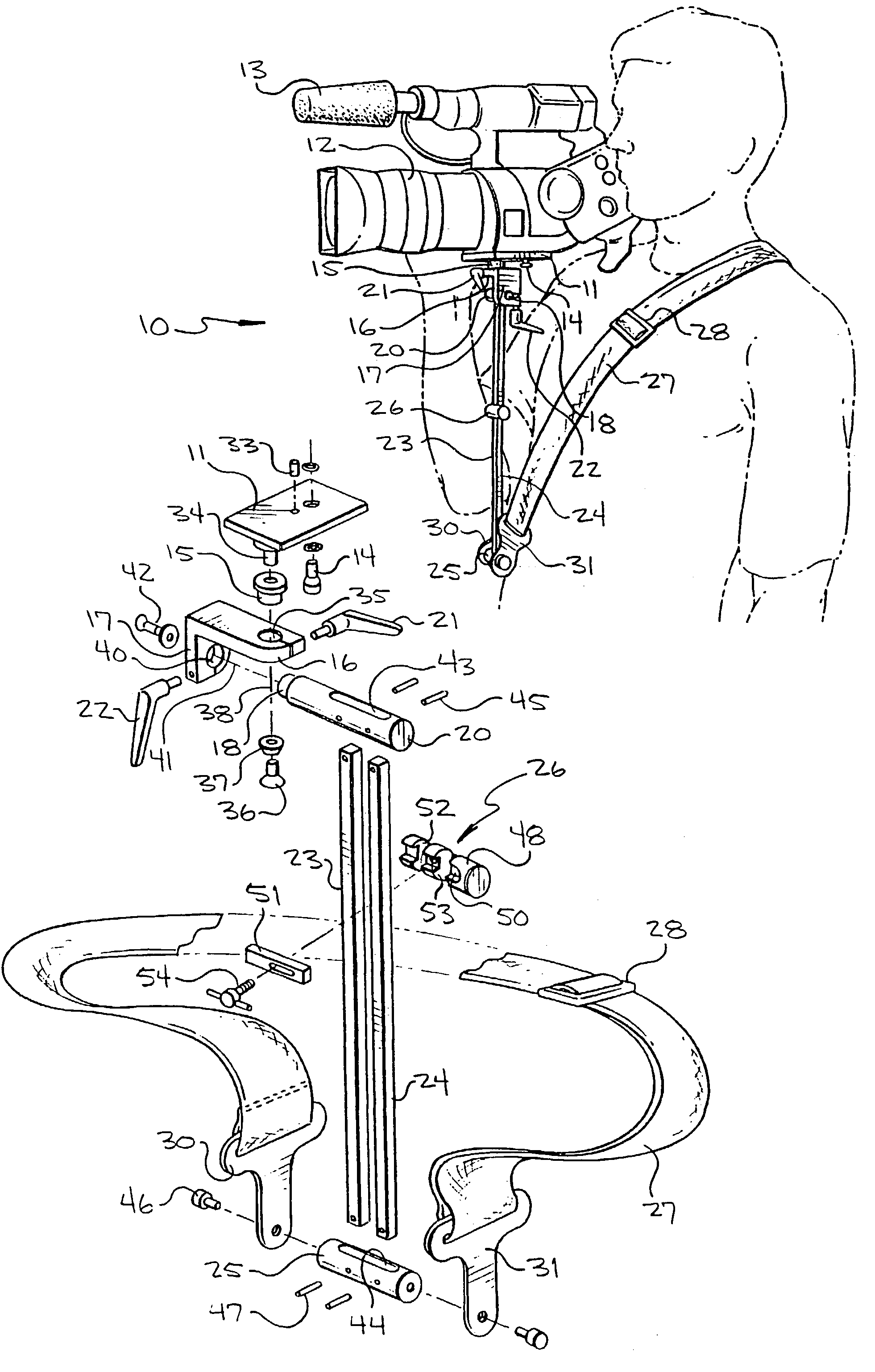
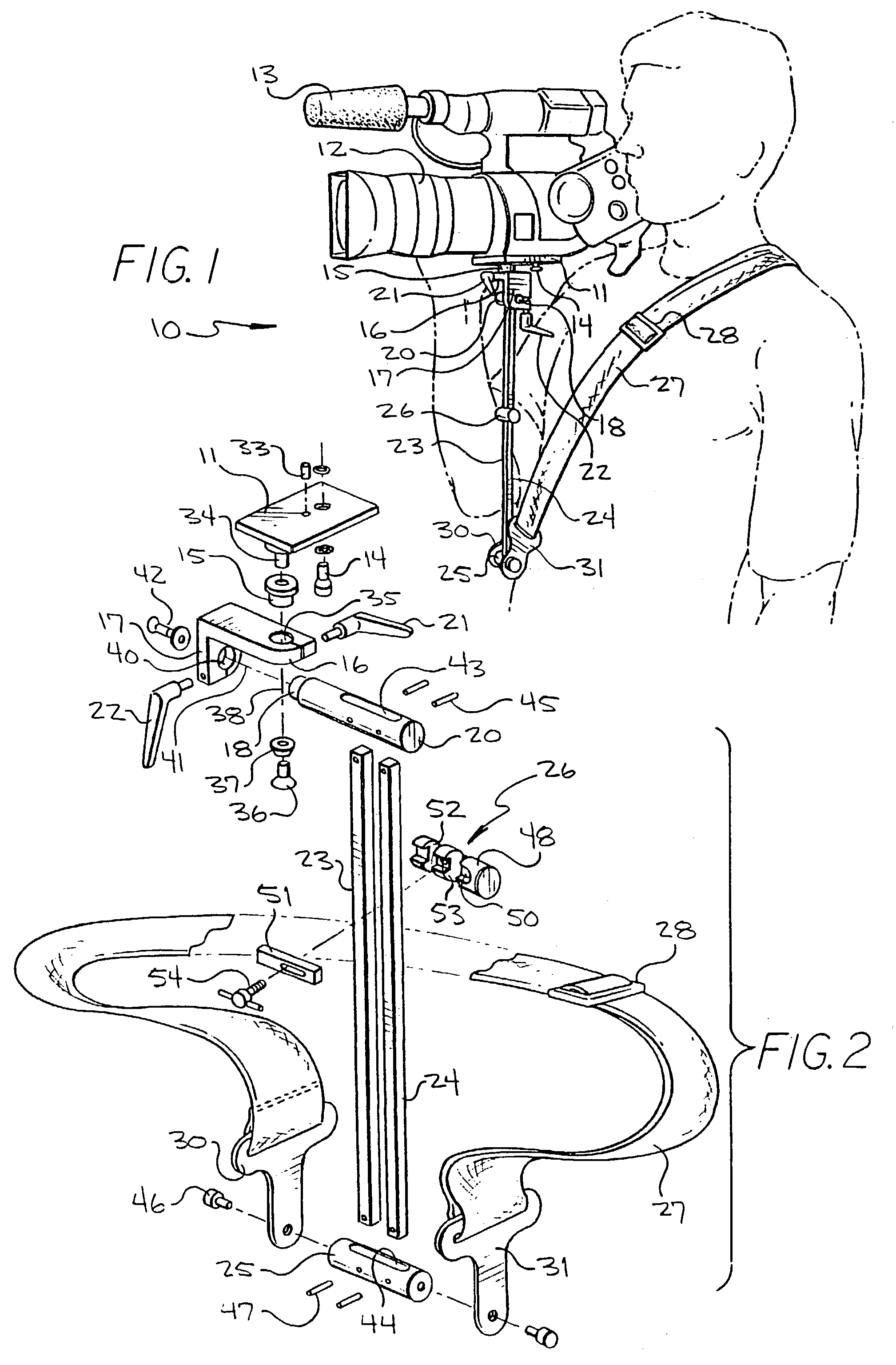
[0023]Referring in detail to FIG. 1, the novel equipment support of the present invention is illustrated in the general direction of arrow 10, which includes an equipment support platform 11 on which equipment such as a camera 12 and audio recording equipment 13 is carried. A fastening screw 14 releasably secures equipment such as the camera 12 onto the surface of the platform 11. The platform 11 is adapted to pivot on a shaft mounted in bearing 15 which is carried on a flange 16 of a double C-clamp 17. The double C-clamp is adapted to rotate about a horizontal axis by means of a bearing 18 carried on the end of an upper or top cross member 20. A securement handle 21 is operably connected between the double C-clamp and the platform for releasably securing the platform in a selected position about a vertical axis. A similar handle 22 is employed for releasably maintaining the platform in a position about a horizontal axis when the double C-clamp is rotated on bearing 18.

[0024]A pair ...


PUM


Abstract

An articulated equipment support includes a pair of elongated support bars, arranged in fixed, spaced-apart relationship, and having their opposite ends joined respectively by a top cross rod and a bottom cross rod. Pivot pins join the opposite ends of the rods to the respective cross bars permitting pivotal, lateral movement of the support bars in unison so that a variety of geometric configurations such as a parallelogram or the like may be achieved. The top cross rod includes an end projection having a bearing surface for rotatably mounting a double C-clamp with an outwardly projecting flange terminating with a bearing for rotatably supporting an equipment platform. An adjustable lock is carried on the platform for releasably securing equipment thereto and a shoulder strap is provided having opposite ends attached to the bottom cross bar and an adjustable mid-section trained across or about the torso of the user.

Description

[0001]Priority Claimed based on Ser. No. 60 / 364,611 filed Mar. 18, 2002BACKGROUND OF THE INVENTION[0002]1. Field of the Invention[0003]The present invention relates to the field of equipment supports intended to be worn on the body of the user, and more particularly to a novel fully articulated equipment support adapted to be carried on the user's torso whereby the equipment may be supported readily positionable between desired locations in front of the user while the equipment is being operated.[0004]2. Brief Description of the Prior Art[0005]In the past, it has been the conventional practice for equipment operators, such as cameramen who support and hold hand-held cameras, recorders or the like, to operate the equipment simultaneously with manual support of the equipment. This, of course, is somewhat awkward and requires considerable dexterity on the part of the operator or cameraman and further requires additional concentration which detracts from the main objective of operating ...

Claims


Application Information

Patent Timeline
Patent Type & Authority Patents(United States)
IPC IPC(8): G03B17/56
CPCF16M11/02F16M11/04F16M11/08G03B17/56F16M13/00F16M13/04F16M11/2057G03B17/561
Inventor KUNDIG, JIM L.
Owner KUNDIG JIM L
Why Eureka
Try Eureka