Machine tool

a technology of machine tools and top covers, applied in the field of machine tools, can solve the problems of preventing efficient change of workpieces on the table, tedious and time-consuming, etc., and achieve the effect of easy opening and closing the top cover

Inactive Publication Date: 2007-03-20
DMG MORI CO LTD
View PDF15 Cites 17 Cited by
  • Summary
  • Abstract
  • Description
  • Claims
  • Application Information

AI Technical Summary

Benefits of technology

[0014]An object of the present invention is therefore to solve this problem by making available a machine tool that enables the operator to easily open and close the top cover without trouble.
[0015]To achieve this object, a machine tool according to the present invention has a bed; a table which is disposed on the bed and on which work is held; a moving component disposed on the bed and provided free to travel at least on a horizontal first axis that is front-to-rear oriented; a main spindle which is supported by the moving component to rotate freely on the main spindle axis and holds a tool; a feed mechanism for moving the table and the moving component relatively on three perpendicular axes including the first axis, and moving the table and main spindle relatively in a machining area; and a cover for covering the machining area by means of a front cover covering a front side of the machining area and first top covers covering a top side of the machining area. The front cover is disposed on the front side of the bed and is furnished with doors that open and close moving on a horizontal second axis perpendicular to the first axis. The first top covers have one end connected to the front side of the moving component to enable movement on the second axis, and the other end connected to the top part of the door of the front cover to extend and retract freely on the first axis and allow the moving component to move on the first axis.

Problems solved by technology

In this situation, however, the doors of this cover may not afford an opening that is large enough to carry the workpiece in and out of the machine tool, thus requiring removing part of the cover.
This prevents efficiently changing the workpiece on the table.
A problem with the machine tool disclosed in Utility Model App. Pub. No. H6-24847, however, is that in order to roll the first top cover to the spindle head and open the part covered by the first top cover, the one end of the first top cover must be disconnected from the front cover and rolled toward the spindle head.
This is tedious and time-consuming.

Method used


Image

  • Machine tool
  • Machine tool
  • Machine tool

Examples


Embodiment Construction

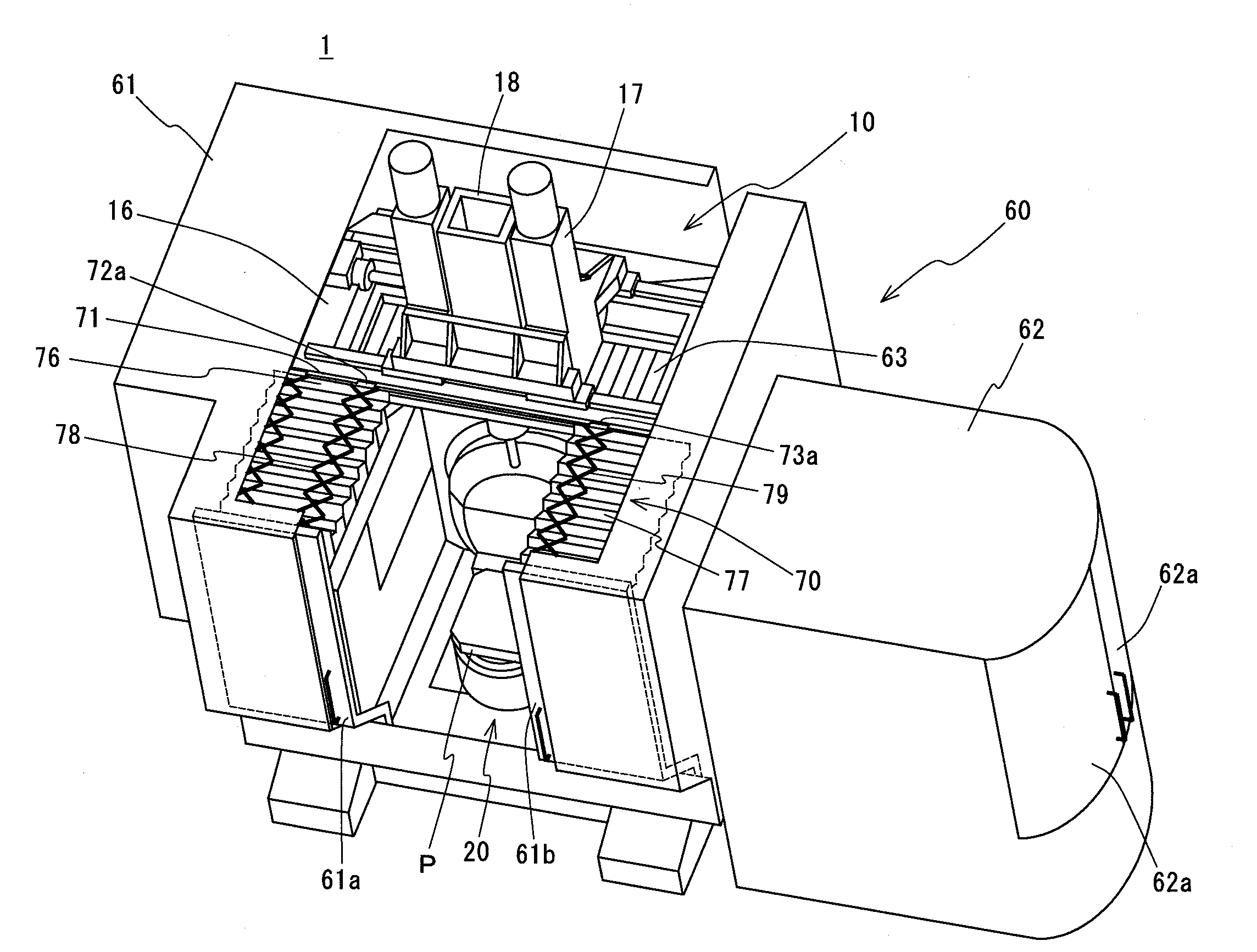
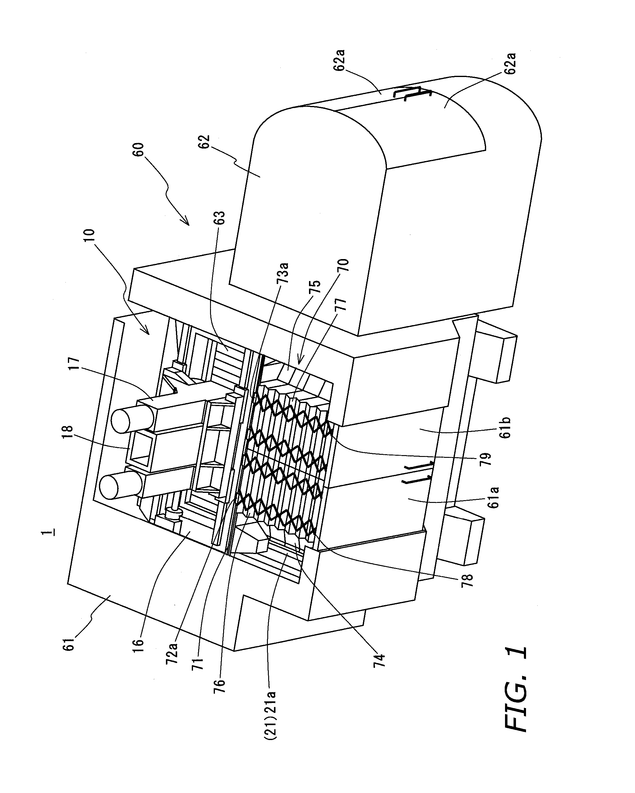
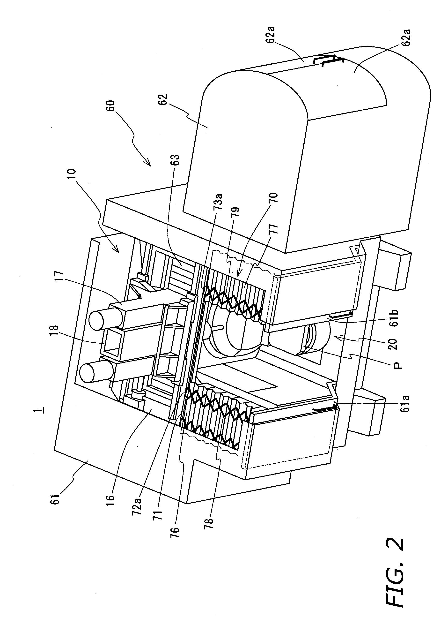
[0040]As shown in FIG. 1 to FIG. 6, a machine tool 1 according to this embodiment of the invention has a machine tool unit 10 of a type known as a vertical machining center, a tool changing device 40, a pallet changing device 45, and a waste recovery device 50 attached to the machine tool unit 10, and a cover 60 covering at least the machine tool unit 10, tool changing device 40, and pallet changing device 45.

[0041]The machine tool unit 10 comprises a bed 11, a first saddle 16 that is disposed on the bed 11 and moves freely back and forth in a horizontal plane (along the Y-axis), a second saddle 17 that is disposed on the first saddle 16 and moves freely in a horizontal plane side to side (along the X-axis), a spindle head 18 that is disposed on the second saddle 17 and moves freely vertically (along the Z-axis), a main spindle 19 that holds a tool T and is supported by the spindle head 18 to rotate freely on the main spindle axis, and a table 20 on which a pallet P is mounted. Work...


PUM

PropertyMeasurementUnit
areaaaaaaaaaaa
timeaaaaaaaaaa
rigidityaaaaaaaaaa

Abstract

Machine tool having a bed, a table arranged on the bed, a first saddle provided free to travel back and forth, a second saddle supported on the first saddle and provided free to travel side to side, a spindle head provided free to travel perpendicularly on the second saddle, a main spindle situated above the table and by the spindle head supported free to rotate on its center axis, a front cover provided on the front side of the bed and furnished with doors that open and close sideways, and top covers configured with one end sideways shiftably connected to the front side of the first saddle, and with another end connected extensibly / retractably to the top of the front-cover doors, therein being configured for permitting back-and-forth-directed movement of the first saddle.

Description

BACKGROUND OF THE INVENTION[0001]1. Technical Field[0002]The present invention relates to machine tools furnished with: a bed; a table on which a workpiece is carried and which is disposed on the bed; a main spindle for retaining a tool, and provided to rotate freely on its center axis; a feed mechanism for shifting the table and the main spindle relatively to each other along three orthogonal axes within the machining area, and a cover for covering the machining area.[0003]2. Description of the Related Art[0004]Such machine tools known to date include the example composed of, primarily: a bed made up of a rectangular base, two sidewalls provided standing along respective right and left sides of the base and opposing each other across an interval; a table on which a workpiece is carried and which is disposed on the base portion of the bed; a cross beam made from a long beam disposed lengthwise between the sides with the longitudinal end parts of the cross beam supported on top of th...

Claims


Application Information

Patent Timeline
Patent Type & Authority Patents(United States)
IPC IPC(8): B23Q11/08
CPCB23Q11/0816B23Q11/0891Y10T74/2193Y10T409/308288Y10T409/30392Y10T483/115B23Q1/012B23Q7/1431
Inventor TAKAYAMA, NAOSHIISHIGAKI, HIKARUAKAI, TAKAYUKIKIMURA, NOBUYUKI
Owner DMG MORI CO LTD
Why Eureka
Try Eureka