Detecting device and method of producing the same

a detection device and a technology of a detection device, applied in the direction of coupling device connection, instruments, coatings, etc., can solve the problems of not being able to connect the rising portion to an external device, deformation or displacement of the rising portion, etc., to prevent deformation of the end, minimize exposure, and ensure the effect of sealing

Inactive Publication Date: 2007-03-20
ALPS ALPINE CO LTD
View PDF10 Cites 12 Cited by
  • Summary
  • Abstract
  • Description
  • Claims
  • Application Information

AI Technical Summary

Benefits of technology

[0007]Accordingly, it is an object of the present invention to provide a detecting device which makes it possible to prevent displacement or deformation of a portion of a terminal that is connected with an external device even if insert-molding is carried out. It is also an object of the present invention to provide a method of producing the detecting device.
[0012]According to the detecting device of the present invention, the terminal has at least one protrusion at the base of the rising portion. The at least one protrusion protrudes up to at least one surface of the terminal lead-out portion in at least one direction that is substantially parallel to a direction perpendicular to the gate side. Accordingly, molding is performed by filling a mold (used for forming the terminal lead-out portion) with resinous material while the end of the protrusion is in contact with an inner surface of the mold. Therefore, even if the base of the rising portion receives a resin flow force during the molding, the protrusion which contacts the mold can prevent deformation of an end of the rising portion that is a connection portion which is connected to an external device.
[0013]In addition, according to the detecting device of the present invention, the at least one protrusion protrudes in two directions included in the at least one direction that is substantially parallel to the direction perpendicular to the gate side. Therefore, it is possible to prevent deformation of the end of the rising portion in a direction of resin flow and in a direction opposite thereto.
[0014]Further, according to the detecting device of the present invention, an end of the at least one protrusion is substantially semicircular. Therefore, it is possible to minimize exposure at a surface of the terminal lead-out portion, so that air-tightness of the housing can be maintained.
[0015]According to the method of producing a detecting device of the present invention, the terminal is insert-molded to the housing by filling the mold with resinous material from the gate while the end of the protrusion of the rising portion is in contact with the lead-out portion formation portion, and the protrusion is disposed in a direction that is substantially parallel to the direction of resin flow. Therefore, even if the base of the rising portion receives a resin flow force, the force can be restricted at the protrusion, so that an end of the rising portion is led out without being displaced or deformed. As a result, the terminal can be integrally formed with high precision.

Problems solved by technology

However, such a related detecting device has the following problems.
When a direction in which the rising portion is led out differs from a direction in which the resin with which the mold is filled flows, the rising portion is pushed by the flow of the resin when the mold is filled with the resin, causing displacement or deformation of the rising portion.
Therefore, it may not be possible to connect the rising portion to an external device because the rising portion is not in correspondence with a connection form of the external device.

Method used


Image

  • Detecting device and method of producing the same
  • Detecting device and method of producing the same
  • Detecting device and method of producing the same

Examples


Embodiment Construction

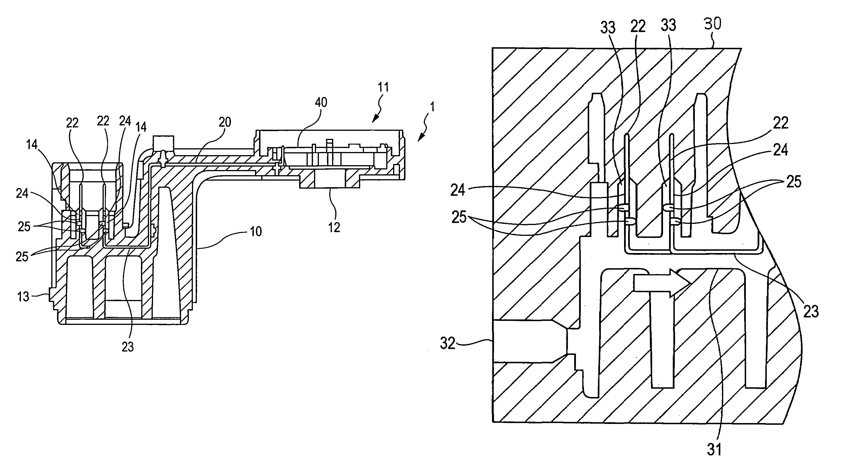
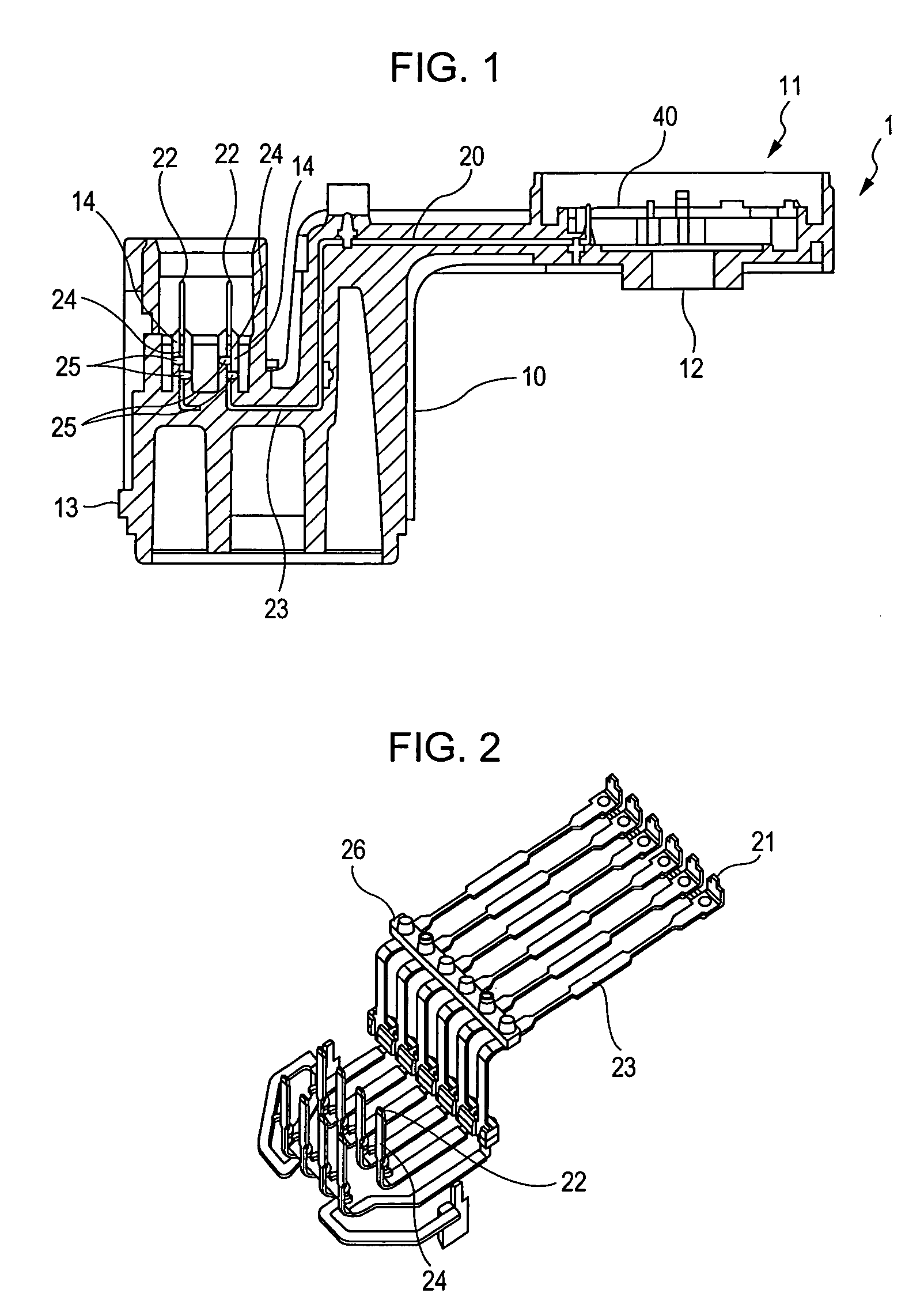
[0020]A detailed description of an embodiment of the present invention will be given with reference to the drawings. FIG. 1 is a sectional view of a detecting device 1 according to the embodiment. As shown in FIG. 1, the detecting device 1 according to the embodiment includes a housing 10 and a terminal 20 integrally formed with the housing 10 by insert molding. A detecting unit which detects a rotation angle of, for example, a rotary valve is mounted to the housing 10. The terminal 20 is electrically connected with the detecting unit and outputs a detected rotation angle signal to an external device.

[0021]The housing 10 has a substantially cylindrical accommodation portion 11 as shown in FIG. 1. A resistance substrate 40, which is a portion of the detecting unit, is secured to the accommodation portion 11. A detection object (not shown), such as a rotary valve, is inserted into a lower portion of the accommodation portion 11. A rotary member having a slider (which is a portion of t...


PUM

PropertyMeasurementUnit
rotation angleaaaaaaaaaa
resistanceaaaaaaaaaa
shapeaaaaaaaaaa

Abstract

A detecting device includes a housing, a detecting unit mounted to the housing, and a terminal insert-molded to the housing. One end of the terminal is electrically connected with the detecting unit, and the other end of the terminal has a rising portion and is led out of the housing. The housing has a gate side and a columnar terminal lead-out portion. The gate side is disposed in correspondence with a gate into which a resinous material is injected during injection molding. The terminal lead-out portion covers a base of the rising portion of the terminal. The terminal has a protrusion at the base of the rising portion. The protrusion protrudes up to a surface of the terminal lead-out portion in a direction that is substantially parallel to a direction perpendicular to the gate side.

Description

BACKGROUND OF THE INVENTION[0001]1. Field of the Invention[0002]The present invention relates to a detecting device including a housing to which a detecting unit is mounted. More particularly, the present invention relates to a detecting device formed by insert molding a terminal (for an outputting operation to the outside) to a housing, and to a method for producing the detecting device.[0003]2. Description of the Related Art[0004]Hitherto, a detecting device which detects a rotation angle of a rotary valve, such as a throttle valve, has detected the rotation angle of the throttle valve by rotating a rotary member together with a shaft of the throttle valve and by bringing the rotary member into contact with a resistance substrate secured to a housing. The rotary member has a slider mounted thereto and is secured to an end of the shaft of the throttle valve.[0005]A terminal is connected to the resistance substrate by, for example, soldering for performing an outputting operation to...

Claims


Application Information

Patent Timeline
Patent Type & Authority Patents(United States)
IPC IPC(8): H01R13/405
CPCB29C45/14639H01R43/24G01D11/245B29C45/14836B29C45/0046B29C45/23B29C45/76B29C45/82
Inventor NAKAGAWA, SHUNICHIASAYAMA, SATOSHI
Owner ALPS ALPINE CO LTD
Why Eureka
Try Eureka