Optical displacement sensor

a technology of optical displacement sensor and optical axis, which is applied in the direction of distance measurement, optical elements, instruments, etc., can solve the problems of increasing the dimensions of the overall displacement sensor, and achieve the effect of preventing dust from impairing the detection capability of the displacement sensor and easy removal of such dus

Inactive Publication Date: 2007-03-20
WISCONSIN ALUMNI RES FOUNDATON +1
View PDF30 Cites 1 Cited by
  • Summary
  • Abstract
  • Description
  • Claims
  • Application Information

AI Technical Summary

Benefits of technology

[0016]Here, one or more filters may be arranged at the exit side of at least one of the slit or slits narrowing one or more light beams projected toward at least one of the distance measurement target or targets, and one or more filters may be arranged at the incident side of at least one of the slit or slits narrowing at least a portion of the light reflected from at least one of the distance measurement target or targets. As a result of such provision of filter(s), in the event that dust accumulates in the vicinity of slit(s), it will be possible to easily remove such dust and it will be possible to prevent such dust from invading the sensor interior from slit(s). This being the case, it will be possible to prevent dust from impairing the detection capability of the displacement sensor.
[0018]Here, one or more filters may be arranged at the exit side of at least one of the slit or slits narrowing one or more light beams projected toward at least one of the distance measurement target or targets. As a result of such provision of filter(s), in the event that dust accumulates in the vicinity of slit(s), it will be possible to easily remove such dust and it will be possible to prevent such dust from invading the sensor interior from slit(s). This being the case, it will be possible to prevent dust from impairing the detection capability of the displacement sensor.

Problems solved by technology

Where light-collecting Fresnel lens 113, light-collecting lens (convex lens) 121, or other such light-collecting element is used, this has presented a problem in that it has been necessary to set the distance between the light-collecting element and the light-receiving element to a prescribed distance; and moreover, the fact that some prescribed size is required for the light-collecting element has caused the dimensions of the overall displacement sensor to increase.

Method used


Image

  • Optical displacement sensor
  • Optical displacement sensor
  • Optical displacement sensor

Examples


embodiment 1

[0026](Embodiment 1)

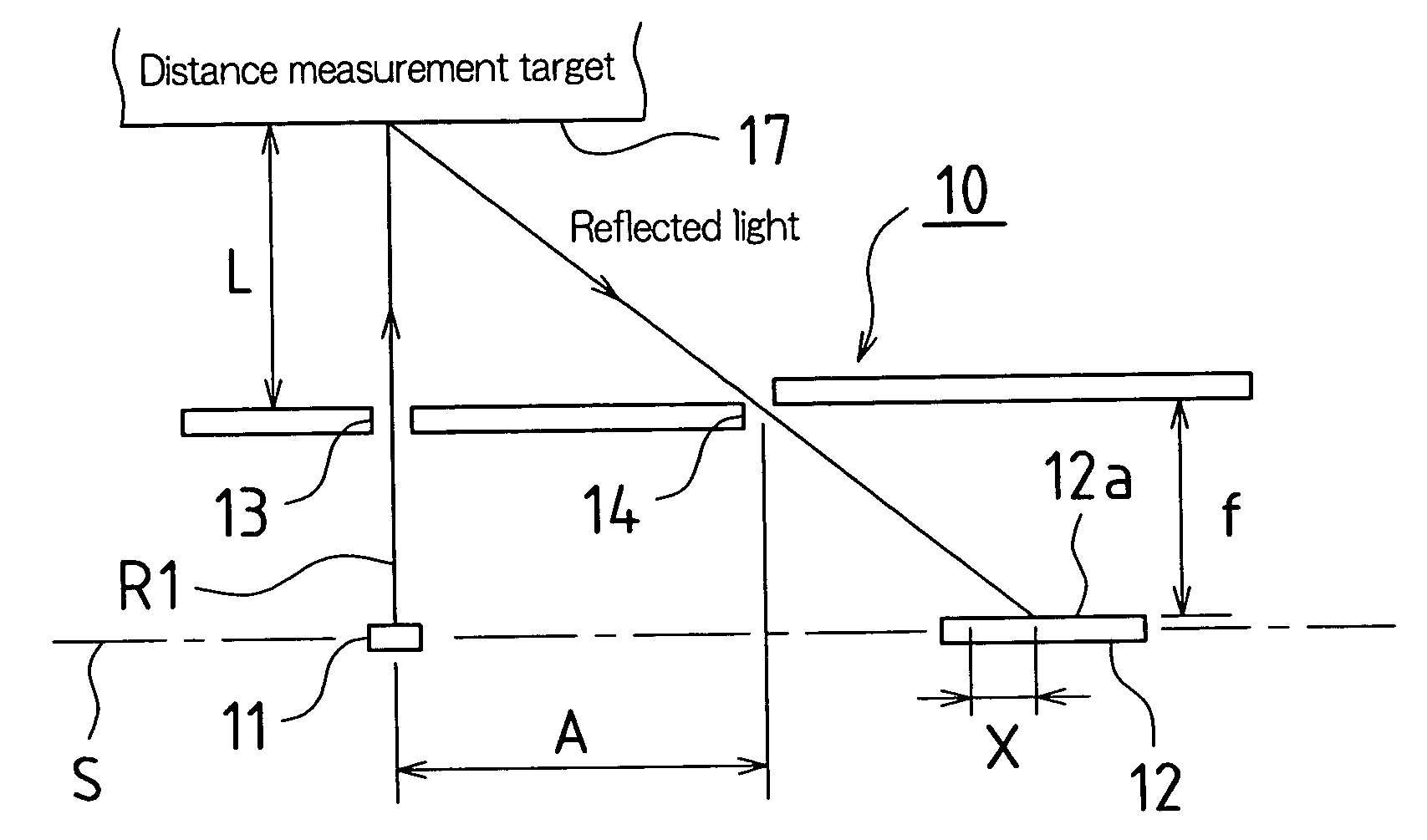
[0027]FIG. 1 is a drawing showing basic constitution of the optics in an optical displacement sensor (hereinafter simply “displacement sensor”) in accordance with the present Embodiment 1.

[0028]This displacement sensor 10, being equipped with light-emitting element 11 and light-receiving element 12 provided along prescribed reference line S, possesses distance measurement range L.

[0029]Light-emitting element 11 is, in the present Embodiment 1, a light emitting diode or other such light source, light beam R1 exiting light-emitting element 11 being narrowed by slit 13, which comprises a small opening disposed in the optical path in front of the region at which light beam R1 exits therefrom, to be projected onto distance measurement target 17.

[0030]Light-receiving element 12 is, in the present Embodiment 1, a PSD (semiconductor position sensing detector), light diffusely reflected by distance measurement target 17 being narrowed by slit 14, which comprises a small o...

embodiment 2

[0037](Embodiment 2)

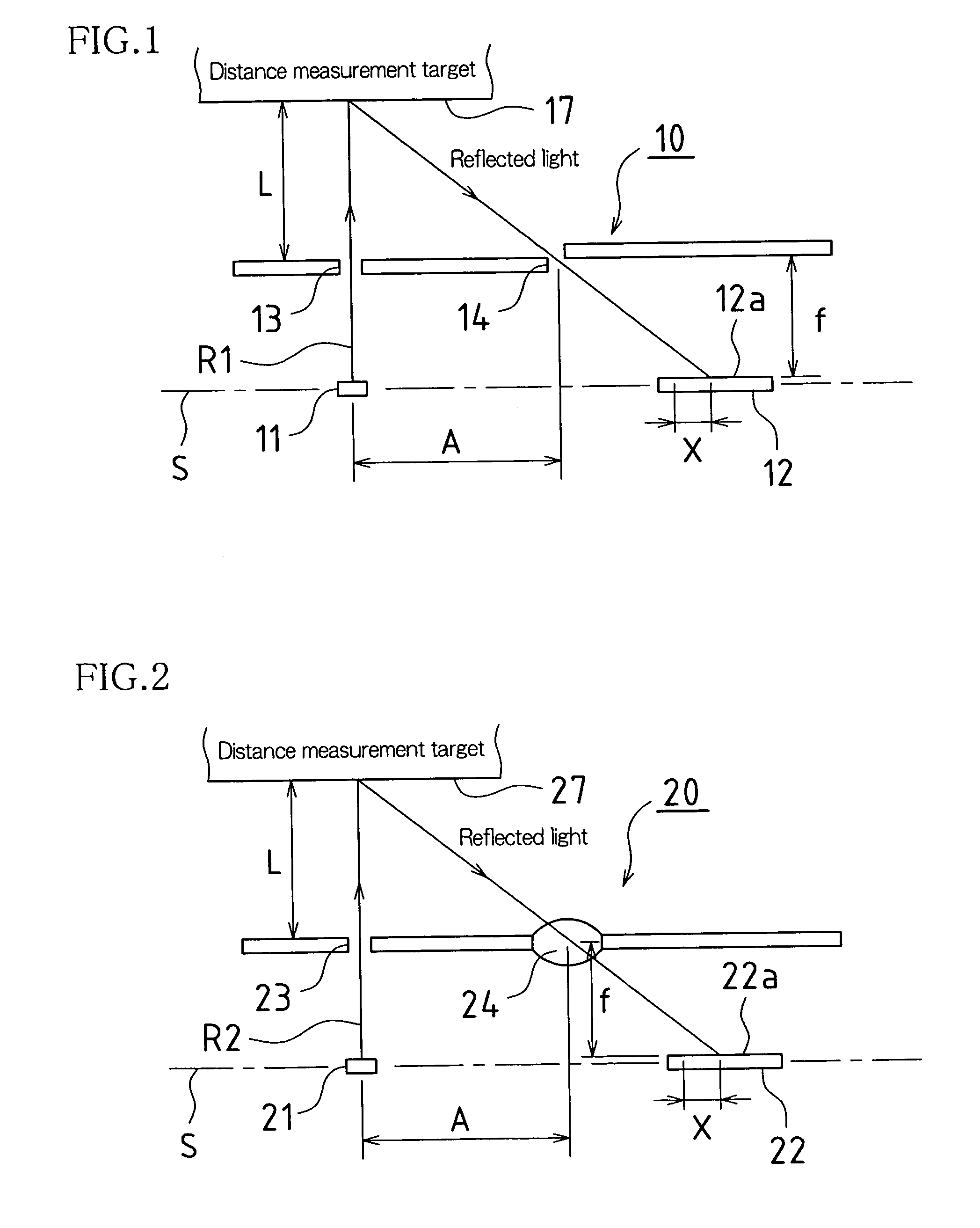
[0038]FIG. 2 is a drawing showing basic constitution of the optics in a displacement sensor 20 in accordance with the present Embodiment 2.

[0039]This displacement sensor 20, being equipped with light-emitting element 21 and light-receiving element 22 provided along prescribed reference line S, possesses distance measurement range L.

[0040]Light-emitting element 21 is, in the present Embodiment 2, a light emitting diode or other such light source, light beam R2 exiting light-emitting element 21 being narrowed by slit 23, which comprises a small opening disposed in the optical path in front of the region at which light beam R2 exits therefrom, to be projected onto distance measurement target 27.

[0041]Light-receiving element 22 is, in the present Embodiment 2, a PSD (semiconductor position sensing detector), light diffusely reflected by distance measurement target 27 being narrowed by light collecting element 24, which is disposed in front of light-receiving surface ...

embodiment 3

[0045](Embodiment 3)

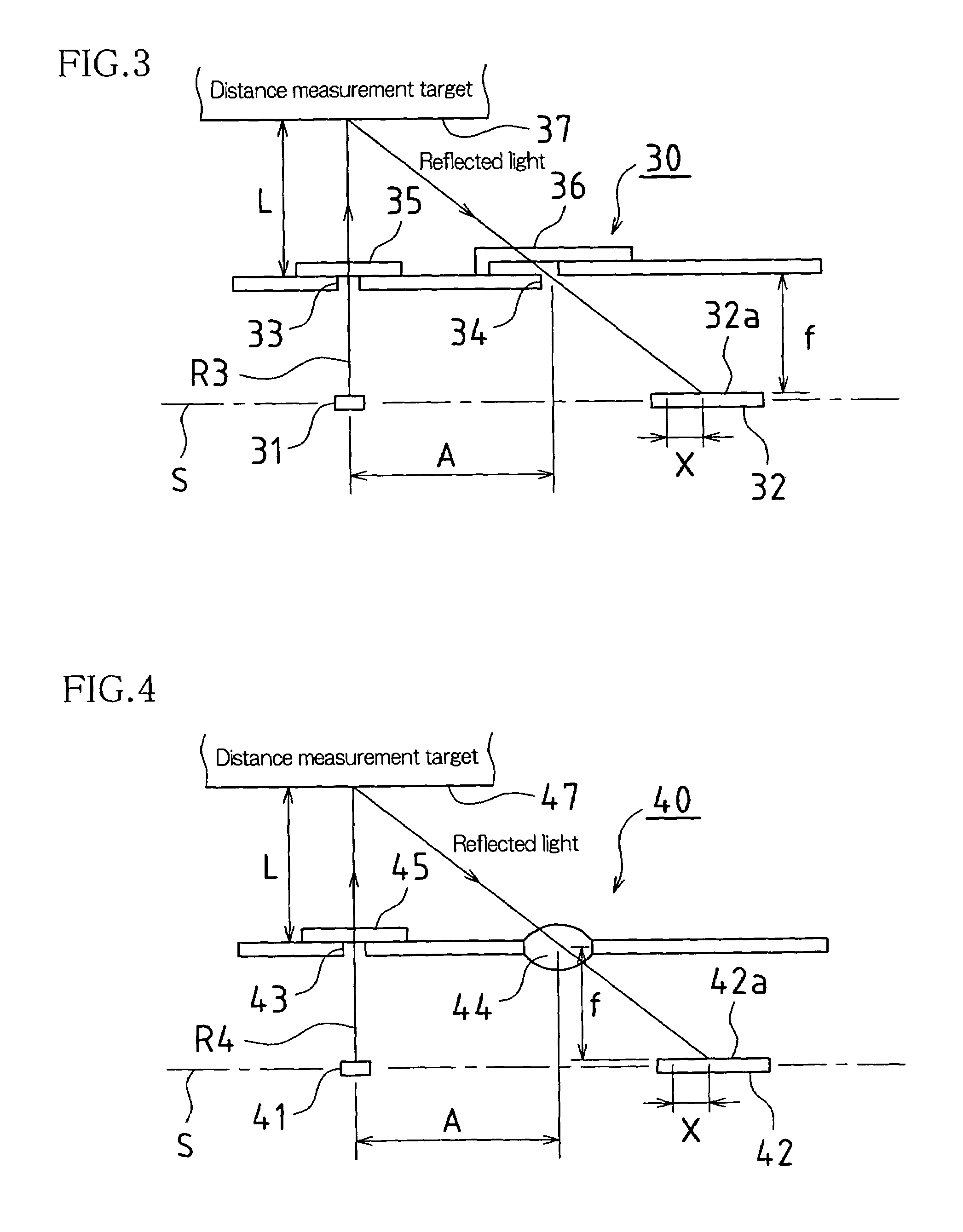
[0046]FIG. 3 is a drawing showing basic constitution of the optics in a displacement sensor 30 in accordance with the present Embodiment 3.

[0047]This displacement sensor 30, being equipped with light-emitting element 31 and light-receiving element 32 provided along prescribed reference line S, possesses distance measurement range L.

[0048]Light-emitting element 31 is, in the present Embodiment 3, a light emitting diode or other such light source, light beam R3 exiting light-emitting element 31 being narrowed by slit 33, which comprises a small opening disposed in the optical path in front of the region at which light beam R3 exits therefrom, and passing through filter 35, which is arranged at the exit side of slit 33, to be projected onto distance measurement target 37.

[0049]Light-receiving element 32 is, in the present Embodiment 3, a PSD (semiconductor position sensing detector), light diffusely reflected by distance measurement target 37 passing through filter ...


PUM


Abstract

Optical displacement sensor may possess light-emitting element(s) for projecting light onto distance measurement target(s), and light-receiving element(s) capable of receiving light reflected from distance measurement target(s) and disposed such that light-receiving surface(s) thereof is or are substantially perpendicular to optical axis or axes R1 of projected light. Furthermore, such optical displacement sensor(s) may be equipped with slit(s) capable of narrowing light beam(s) projected toward distance measurement target(s), and slit(s) capable of narrowing light reflected from distance measurement target(s).

Description

CROSS-REFERENCE TO RELATED APPLICATION / PRIORITY[0001]The present application claims right of benefit of prior filing date of Japanese Patent Application No. 2002-280877, the content of which is incorporated herein by reference in its entirety. Furthermore, all references cited in the present specification are specifically incorporated herein by reference in their entirety.BACKGROUND OF INVENTION[0002]1. Field of the Invention[0003]The present invention pertains to an optical displacement sensor capable of detecting displacement of a target to which distance is measured by projecting light and receiving such light after reflection thereof.[0004]2. Related Art[0005]Triangulation-type displacement sensors capable of detecting displacement of a target to which distance is measured by projecting light and receiving such light after reflection thereof have been proposed conventionally (e.g., see Japanese Patent Application Publication Kokai No. H4-174923 (1992) and Japanese Patent Applica...

Claims


Application Information

Patent Timeline
Patent Type & Authority Patents(United States)
IPC IPC(8): G01B11/14G02B27/40G01B11/00G01C3/08G01D5/28
CPCG01D5/28G01C3/085
Inventor NAKANO, TAKAHIKO
Owner WISCONSIN ALUMNI RES FOUNDATON
Why Eureka
Try Eureka