

Method of assembling a disk drive including actuating a shipping comb to bend a suspension vertically to facilitate a merge tool
a technology of a shipping comb and a disk drive, which is applied in the direction of mounting the head within the housing, recording information storage, instruments, etc., can solve the problems of particle contamination, damage to the suspension, and affect other drives, so as to reduce friction between the fingers
- Summary
- Abstract
- Description
- Claims
- Application Information
AI Technical Summary
Benefits of technology
Problems solved by technology
Method used
Image

Examples
Embodiment Construction
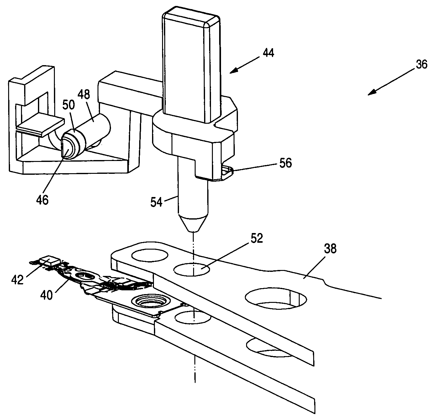
[0025]FIG. 4A shows an isometric, exploded view of a head stack assembly (HSA) 36 according to an embodiment of the present invention for use in a disk drive comprising a disk, wherein a merge tool is used to merge the HSA 36 with the disk during manufacturing of the disk drive. The HSA 36 comprises at least one actuator arm 38, and a suspension 40 connected to a distal end of the actuator arm 40. A head 42 is connected to a distal end of the suspension 40. A multi-level shipping comb 44 is attached to the actuator arm (FIG. 4B), wherein the multi-level shipping comb 44 comprising at least one finger 46 that limits relative vertical motion of the suspension 40. The finger 46 comprises a first surface 48 and a second surface 50, wherein the second surface 50 is raised relative to the first surface 48. During shipping of the HSA, the first surface 48 of the finger 46 contacts the suspension 40 to protect against overstressing the suspension 40. During manufacture of the disk drive, th...
PUM
 Abstract
Description
Claims
Application Information