
Blade server system

a server system and blade technology, applied in the field of blade server system, can solve the problems of re-repairing the mid-plane or the module that is relatively time-consuming, and achieve the effect of convenient removal and easy maintenan

Active Publication Date: 2007-03-20
QUANTA COMPUTER INC
View PDF5 Cites 24 Cited by
  • Summary
  • Abstract
  • Description
  • Claims
  • Application Information

AI Technical Summary

Benefits of technology

The invention is a blade server system with a rear module chassis that can hold various component modules shared among all the server blades. The rear module chassis has partitions to easily remove and maintain individual component modules without needing to remove other modules. The mid-plane is mounted to the rear module chassis, so when the rear module chassis is removed, the mid-plane is removed simultaneously, making maintenance easier.

Problems solved by technology

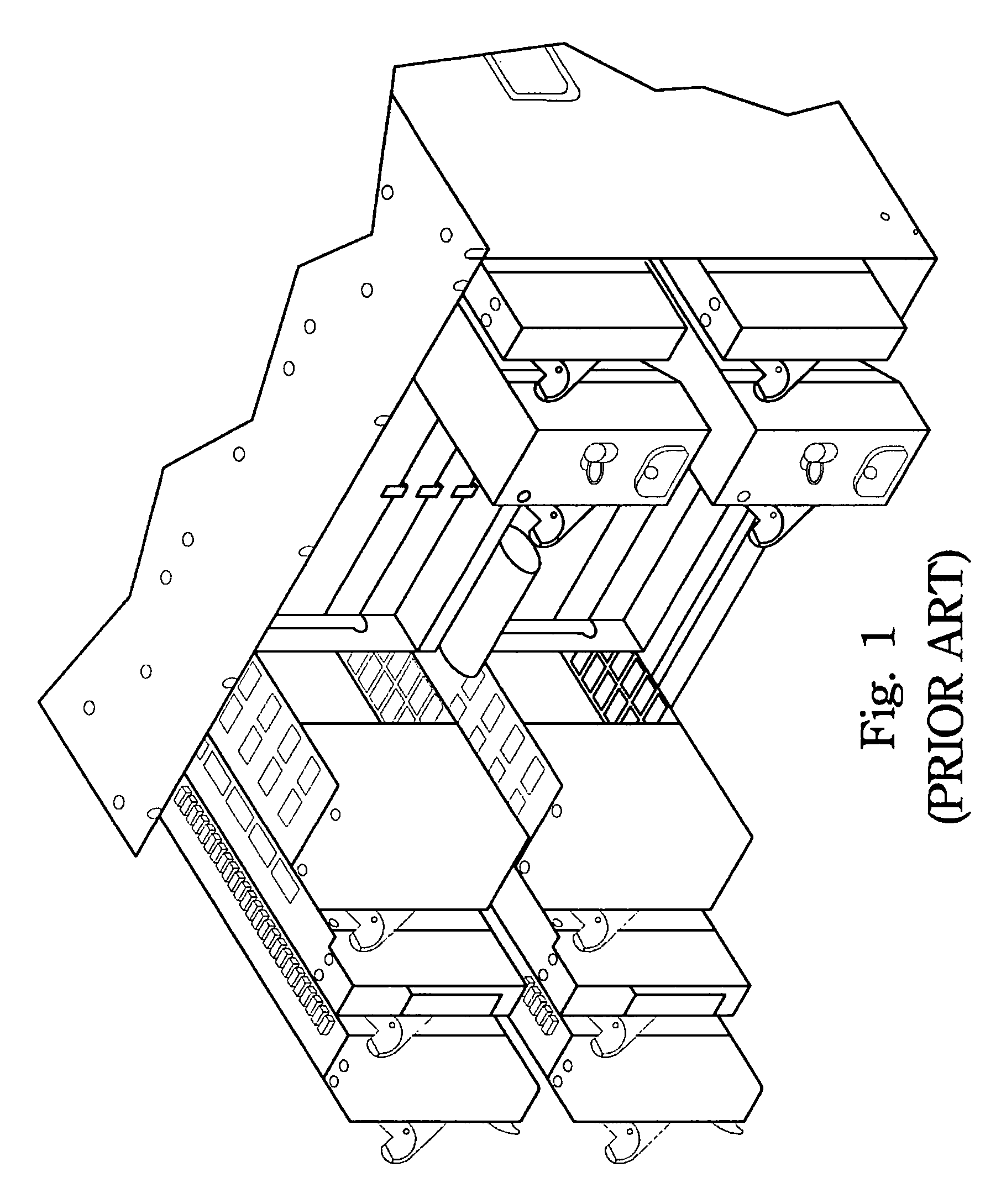
Likewise, when maintenance is performing on one of the modules, other modules may obstruct the removal of a single module, such that the neighboring modules may need to be removed in order to properly remove the module intended to be maintained.
Accordingly, it is relatively time-consuming to repair the mid-plane or the modules due to the inconvenient process of removing and re-assembling the various components.

Method used


Image

  • Blade server system
  • Blade server system
  • Blade server system

Examples


Embodiment Construction

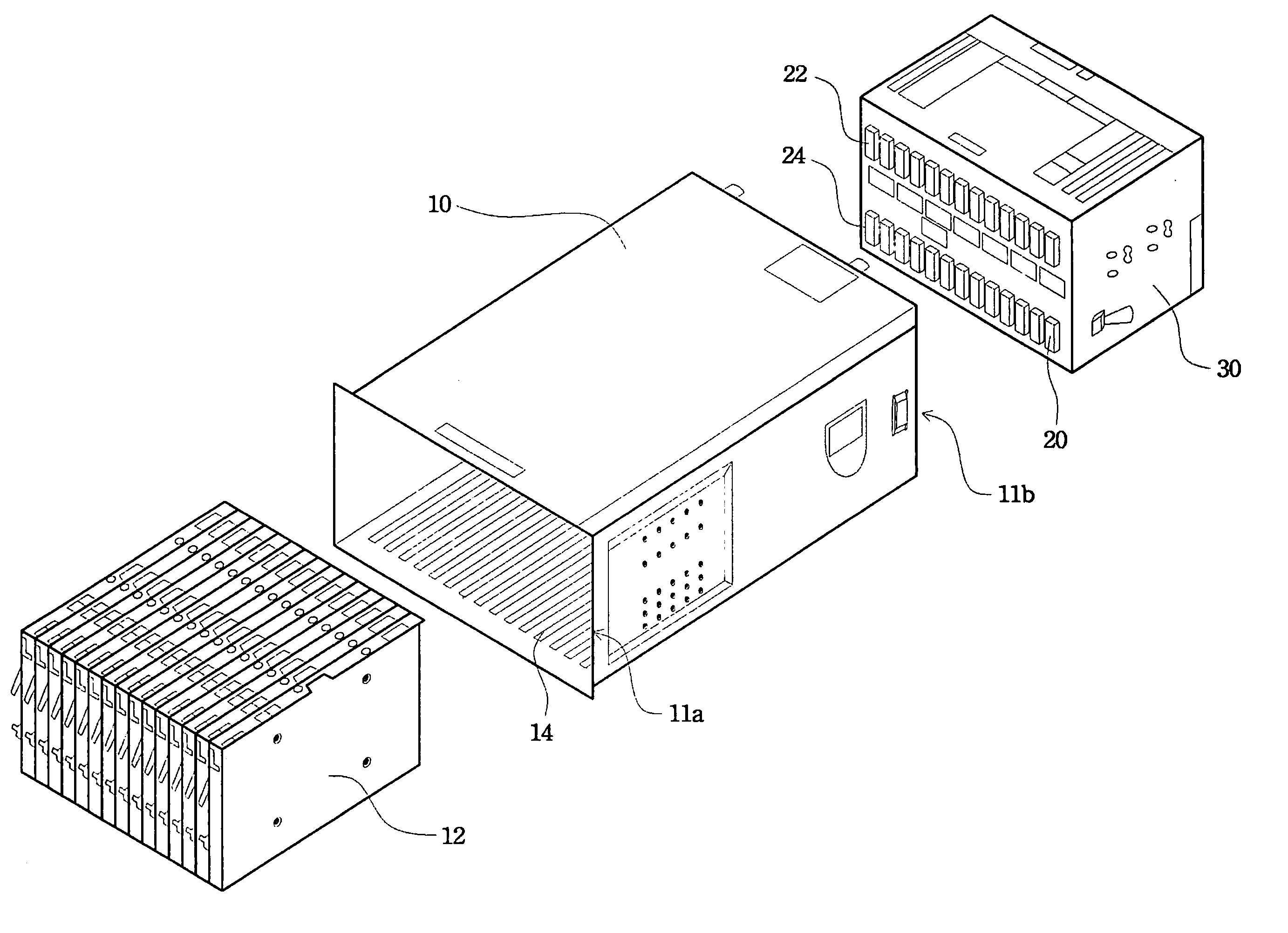
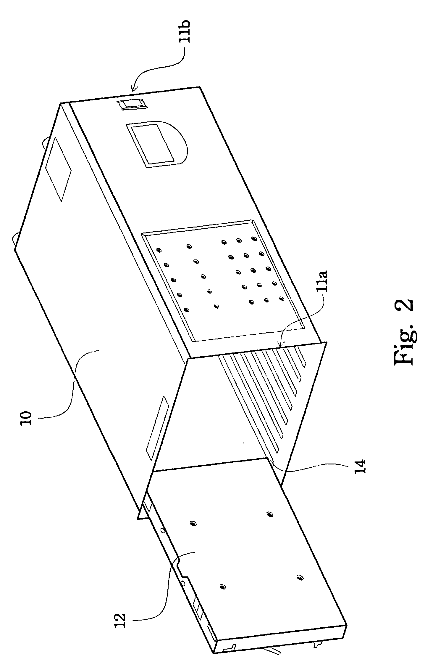
[0020]FIG. 2 is a perspective view of the overall appearance of the blade server system according to the present invention. Referring to this figure, a main chassis 10 houses all the components of the server blade system. The main chassis 10 has a front end 11a and an opposite rear end 11b. Only one blade 12 is depicted in FIG. 2 to slide into the main chassis 10 through its front end 11a for clear illustration. There, however, may be up to fourteen server blades or processor blades that are hot pluggable into the slots 14 through the front end of the main chassis 10. The term “server blade” or “processor blade”, or simply “blade” is used throughout the specification and claims, but it should be understood that these terms are not limited to blades that only perform “processor” or “server” functions, but also include blades that perform other functions, such as storage blades, which typically include hard disk drives and whose primary function is data storage.

[0021]FIG. 3 is a persp...


PUM


Abstract

A blade server system is described. The blade server system includes a main chassis, a rear module chassis and a mid-plane. The main chassis is formed with slots into which a plurality of sever blades are slidablely inserted from the front end of the main chassis. The rear module chassis is removablely mounted to the rear end of the main chassis, and divided into plural partitions for housing different component modules. The mid-plane is mounted to an end of the rear module chassis, and includes a first face and an opposite second face. The first face has plural connectors electrically connected to the server blades and the second face has plural connectors electrically connected to the component modules. Therefore, when maintenance is needed for the mid-plane, the service engineer only needs to withdraw the entire rear module chassis as a whole, without the need to remove the individual component modules.

Description

CROSS-REFERENCE TO RELATED APPLICATION[0001]Not ApplicableSTATEMENT REGARDING FEDERALLY SPONSORED RESEARCH OF DEVELOPMENT[0002]Not ApplicableBACKGROND OF THE INVENTION[0003]1. Field of the Invention[0004]The present invention relates to a blade server system, and more particularly, to a blade server system with a detachable rear module chassis for housing component modules and mounting a mid-plane to allow easy maintenance.[0005]2. Description of the Related Art[0006]The present invention pertains to computers and other information processing systems and, more particularly, to a blade server system.[0007]Conventional blade server systems include a main chassis into which a plurality of “sever blades” is slidablely insert 22d into slots in the front of the main chassis. The server blades are usually hot pluggable, they can be removed from the main chassis without the need to shut down the chassis and all its components. Each server blade includes the majority of the components of a c...

Claims


Application Information

Patent Timeline
Patent Type & Authority Patents(United States)
IPC IPC(8): G06F1/20G06F1/26
CPCH05K7/1445H05K7/1488Y10T16/527
Inventor LIANG, YUAN-CHENLIU, YUNG-LUNGLU, HSUEH-CHINCHEN, CHAO-JUNG
Owner QUANTA COMPUTER INC
Learn More