Sound masking system

a sound masking and sound technology, applied in the field of sound masking systems, can solve the problems of unwanted speech of a talker in a nearby workstation area readily transmitted to unintended listeners in nearby workstation areas, easily becomes a source of annoyance itself, and the volume of the masking sound must be a relatively high intensity, so as to achieve superior sound masking and low directivity index

Inactive Publication Date: 2007-03-20
CAMBRIDGE SOUND MANAGEMENT
View PDF33 Cites 55 Cited by
  • Summary
  • Abstract
  • Description
  • Claims
  • Application Information

AI Technical Summary

Problems solved by technology

However, despite the advantages of the open plan type office, unwanted speech from a talker in a nearby workstation is readily transmitted to unintended listeners in nearby workstation areas.
By contrast, if it has any readily identifiable or unnatural characteristics such as “rumble,”“hiss,” or tones, or if it exhibits obvious temporal variations of any type, it readily becomes a source of annoyance itself.
However, the volume of the masking sound must be a relatively high intensity if the construction NR is reduced by partial-height intervening partitions, an acoustically poor design or layout, or materials that have a high acoustic reflectivity.
Even in an acoustically well designed open office, the level of masking noise necessary to meet privacy goals may be judged uncomfortable by some individuals, especially those with certain hearing impairments.
Naturally generated air noise from an HVAC system typically is radiated by many spatially separated turbulent eddies generated at the system terminal devices or diffusers.
In contrast, even if a masking system provides an ideal spectrum shape and sound level, its quality will be unpleasantly “canned” or colored subjectively if it is radiated from a single loudspeaker or location.
In addition, the sound attenuation characteristics of the ceiling assembly are normally not knowable until after installation and testing.
Thus, additional time and cost are incurred due to the testing and frequency adjustment that must be performed post installation.
Also, because the acoustic sound masking signal must pass through the acoustical ceiling and be attenuated thereby, a large part of the acoustical power radiated by the loudspeakers is wasted in the form of heat as the acoustic masking signal is attenuated.
Accordingly, despite the requirement for only very small amounts of acoustical sound masking power within the listening space itself, relatively high power electrical signals driving large and costly loudspeakers are needed to provide the necessary masking signal strength.
Due to the power required, the loudspeaker assemblies are normally large and heavy.
This additional support structure increases the installation cost, and the placement of the large loudspeakers in the plenum area inhibits access to the above ceiling space, which also complicates the design and installation of the loudspeakers.
However, their use has been restricted to installation in facilities with atypically high ceiling heights due to appearance, masking sound uniformity, an overly small or crowded plenum area, and cost considerations.
When a conventional loudspeaker is attempted below a ceiling in a more typical office environment with ceiling heights of 9′–12′, or within the ceiling, the uniformity of masking sound is found to be unacceptable.
In particular, conventional loudspeakers exhibit a narrow beamwidth at higher frequencies, causing “hot-spotting” on their axes.
Unlike music or other time varying signals, masking sound has essentially constant bandwidth temporally, and any significant narrowing of beamwidth within the acoustic band is immediately obvious and unpleasant to most individuals.
Moreover, unless loudspeakers are mounted within several feet of one another, overall level uniformity is unacceptable due to square law or distance spreading, that is, the sound level attenuates unacceptably with distance from the loudspeaker, drawing attention to its location.
This close loudspeaker proximity is unsightly and uneconomic.
Thus, in these systems an unacceptable number of these conventional loudspeakers are required to avoid hot-spotting and signal non-uniformity within a masking zone.
As masking levels are increased above 48 dBA, complaints of excessive masking sound increase.
Unfortunately, it can be shown that this level of sound with the typically used spectrum is largely ineffective for sound masking in an office setting without significant acoustical barriers to reduce high frequencies of intruding speech sound.

Method used


Image

  • Sound masking system
  • Sound masking system
  • Sound masking system

Examples


Embodiment Construction

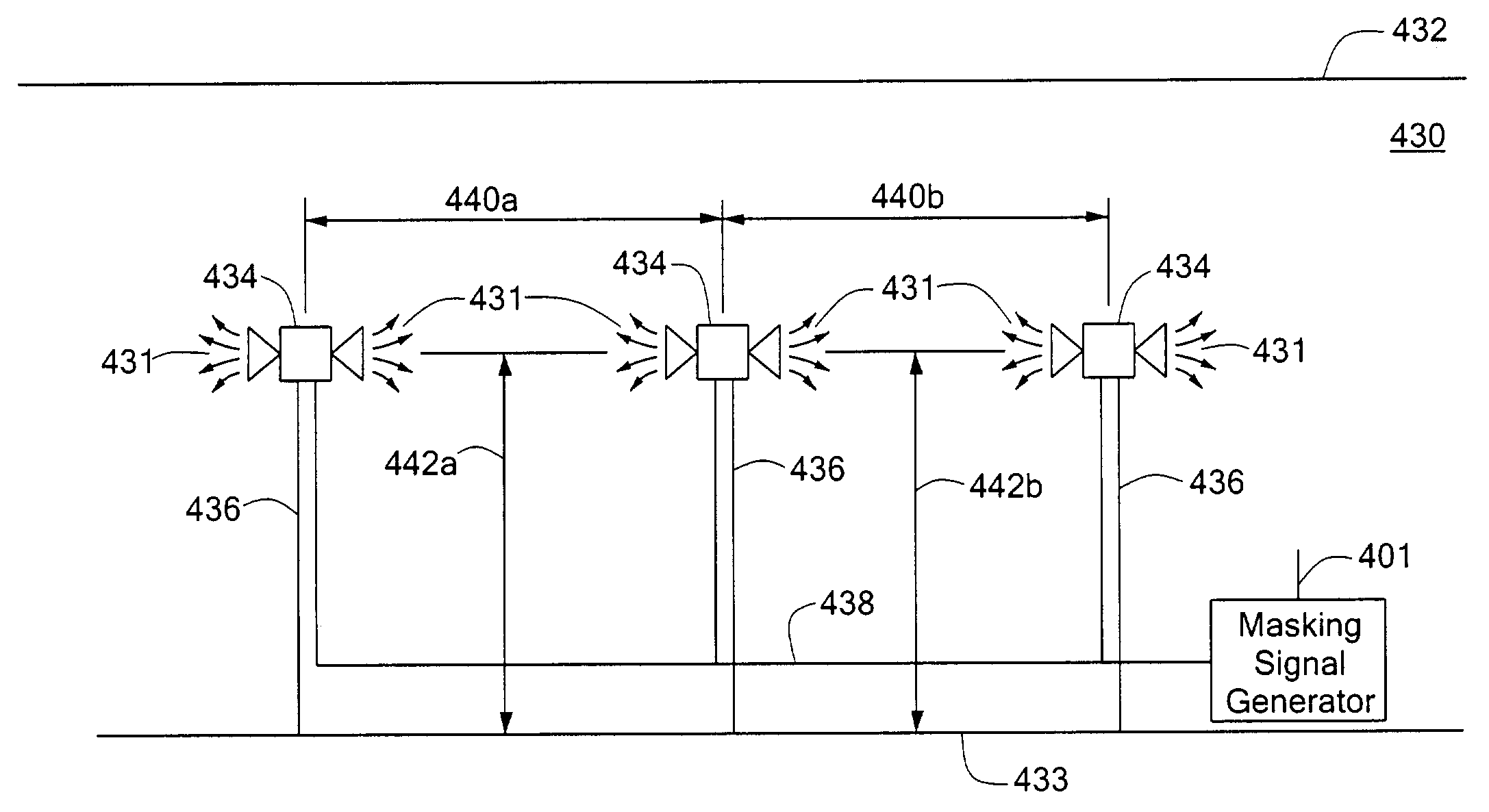
[0036]In a sound masking system according to the invention, one or more sound masking loudspeaker assemblies are coupled to one or more electronic sound masking signal generators. The loudspeaker assemblies in the system of the invention have a low directivity index and, preferably, emit an acoustic sound masking signal that has a sound masking spectrum specifically designed to provide superior sound masking in an open plan office. Each of the plurality of loudspeaker assemblies is oriented to provide the acoustic sound masking signal in a direct path into the predetermined area in which masking sound is needed. In addition, the sound masking system of the invention can include a remote control function by which a user can select one of a plurality of stored sets of information for providing from a recipient loudspeaker assembly an acoustic sound masking signal having a selected sound masking spectrum stored in the sound masking signal generator. One of the stored plurality of sets ...


PUM


Abstract

A sound masking system according to the invention is disclosed in which one or more sound masking loudspeaker assemblies are coupled to one or more electronic sound masking signal generators. The loudspeaker assemblies in the system of the invention have a low directivity index and preferably emit an acoustic sound masking signal that has a sound masking spectrum specifically designed to provide superior sound masking in an open plan office. Each of the plurality of loudspeaker assemblies is oriented to provide the acoustic sound masking signal in a direct path into the predetermined area in which masking sound is needed. In addition, the sound masking system of the invention can include a remote control function by which a user can select from a plurality of stored sets of information for providing from a recipient loudspeaker assembly an acoustic sound masking signal having a selected sound masking spectrum.

Description

CROSS REFERENCE TO RELATED APPLICATIONS[0001]The present application claims priority under 35 USC §119(e) of U.S. Provisional Application No. 60 / 345,362 titled Sound Masking System, filed Oct. 24, 2001, which is hereby incorporated by reference herein.STATEMENT REGARDING FEDERALLY SPONSORED RESEARCH OR DEVELOPMENT[0002]N / ABACKGROUND OF THE INVENTION[0003]This invention relates to sound masking systems and, in particular, to sound masking systems for open plan offices.[0004]Freedom from distraction is an important consideration for workers' satisfaction with their office environment. In a conventional enclosed office with full height partitions and doors, any speech sound intruding from outside the office is attenuated or inhibited by the noise reduction (NR) qualities of the wall and ceiling construction. Background noise, such as from the building heating or ventilating (HVAC) system, typically masks or covers up residual speech sound actually entering the office. Under normal circ...

Claims


Application Information

Patent Timeline
Patent Type & Authority Patents(United States)
IPC IPC(8): H04R3/02G10K11/175H04R1/02H04R27/00
CPCH04R1/025H04R27/00H04R2201/021H04K3/825H04K2203/12H04K3/42H04K3/43H04K3/45H04K2203/34G10K11/1754
Inventor HORRALL, THOMAS R.HEINE, JOHN C.
Owner CAMBRIDGE SOUND MANAGEMENT
Why Eureka
Try Eureka