Method for automatically decomposing dynamic system models into submodels

a dynamic system model and submodel technology, applied in the field of automatic decomposition of dynamic system models into submodels, can solve problems such as the possibility of errors being introduced into the submodel, the simulation to halt prior to successful completion, and the speed up of more complex simulations, so as to facilitate communication and avoid deadlock

Inactive Publication Date: 2007-03-20
AGILENT TECH INC
View PDF4 Cites 22 Cited by
  • Summary
  • Abstract
  • Description
  • Claims
  • Application Information

AI Technical Summary

Benefits of technology

[0014]Several advantages may be associated with various embodiments of the invention. Since the generation of the system submodels is performed automatically, the possibility of mistakes being introduced into the system submodels is essentially eliminated. Also, all software that must be added to the software submodels to facilitate communication between the various submodels is generated automatically. Additionally, since the system model is employed directly to generate the system submodels, consistent timing parameters and block priorities between functional blocks within and between each submodel are maintained to avoid deadlock. Furthermore, since the system submodels are generated automatically from the system model, all changes to the system may be made solely at the system model level; changes to the submodels are taken care of automatically whenever the system submodels are built.

Problems solved by technology

Dynamic systems, which are human-devised systems that respond in some beneficial way to changing conditions within their environment, represent a significant challenge to the designers of such systems due to the myriad and diverse conditions such systems must be capable of handling effectively.
However, many dynamic systems being developed today are not monolithic; that is, such systems often are implemented by way of a mixture of different types of hardware and software, each performing some different function.
Additionally, breaking a simulation into several “submodels,” each running on a separate platform, may also speed up more complex simulations, as the processing required would be distributed across multiple platforms running concurrently.
Unfortunately, several problems arise as a result of manually generating the submodels.
First, the process of generating the system submodels from the system model by hand leads to the possibility of errors being introduced into the submodels, as no automated connection exists between the original system model 1 and the submodels.
Otherwise, a simulation across the various software submodels may result in deadlock, which causes the simulation to halt prior to successful completion.
Thus, unless each submodel is configured to accept the proper datatype, proper execution of the submodel is not likely, as that input data may be misinterpreted.
These problems result from the separate system submodels being manually generated, as each such submodel is not generated and validated within the environment of the system model 1 as a whole.
Also, changes made in the system model 1 are not reflected in earlier-generated system submodels, and vice-versa, resulting in separate, painstaking maintenance of both the system model 1 and system submodels.

Method used


Image

  • Method for automatically decomposing dynamic system models into submodels
  • Method for automatically decomposing dynamic system models into submodels
  • Method for automatically decomposing dynamic system models into submodels

Examples


Embodiment Construction

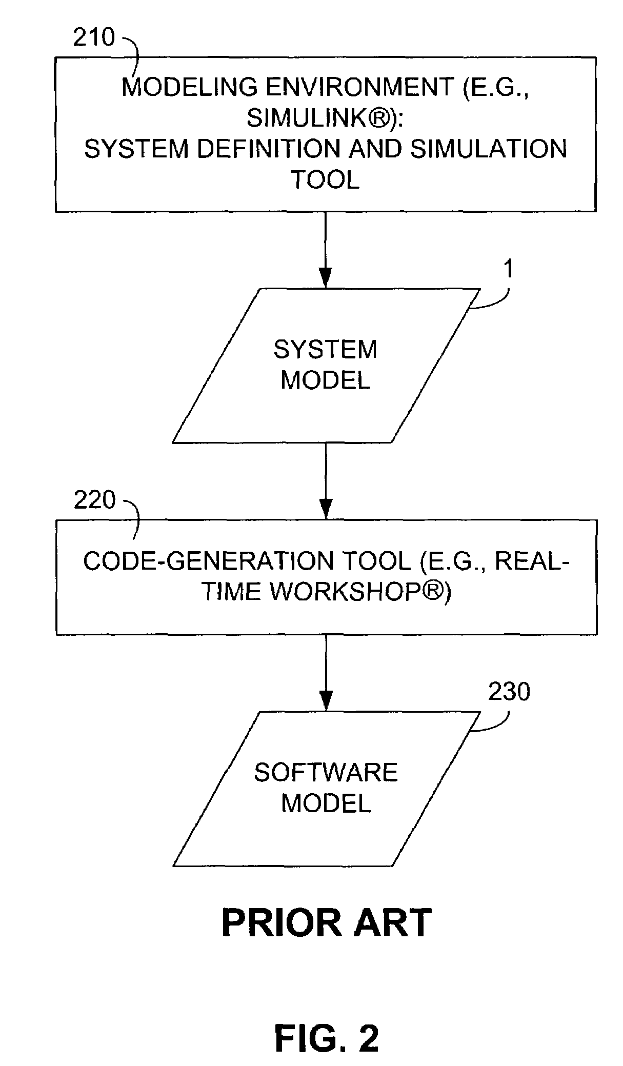
[0022]Embodiments of the invention, as described in detail below, utilize as a starting point the Mathworks Simulink® modeling environment described above. However, other simulation model environments may be employed in a similar fashion as the basis for alternate embodiments of the present invention.

[0023]Furthermore, the software of alternate embodiments of the invention may be manifested in varying levels of integration with the associated modeling environment. For example, alternate embodiments may include distinct follow-on software that is installed separately from the modeling environment. Other embodiments, like those specifically discussed herein, may involve software developed independently, but integrated within the modeling environment. Also, other embodiments may represent code that is highly integrated to the point that such code is indistinguishable by an outside observer from that which comprises the remainder of the modeling environment.

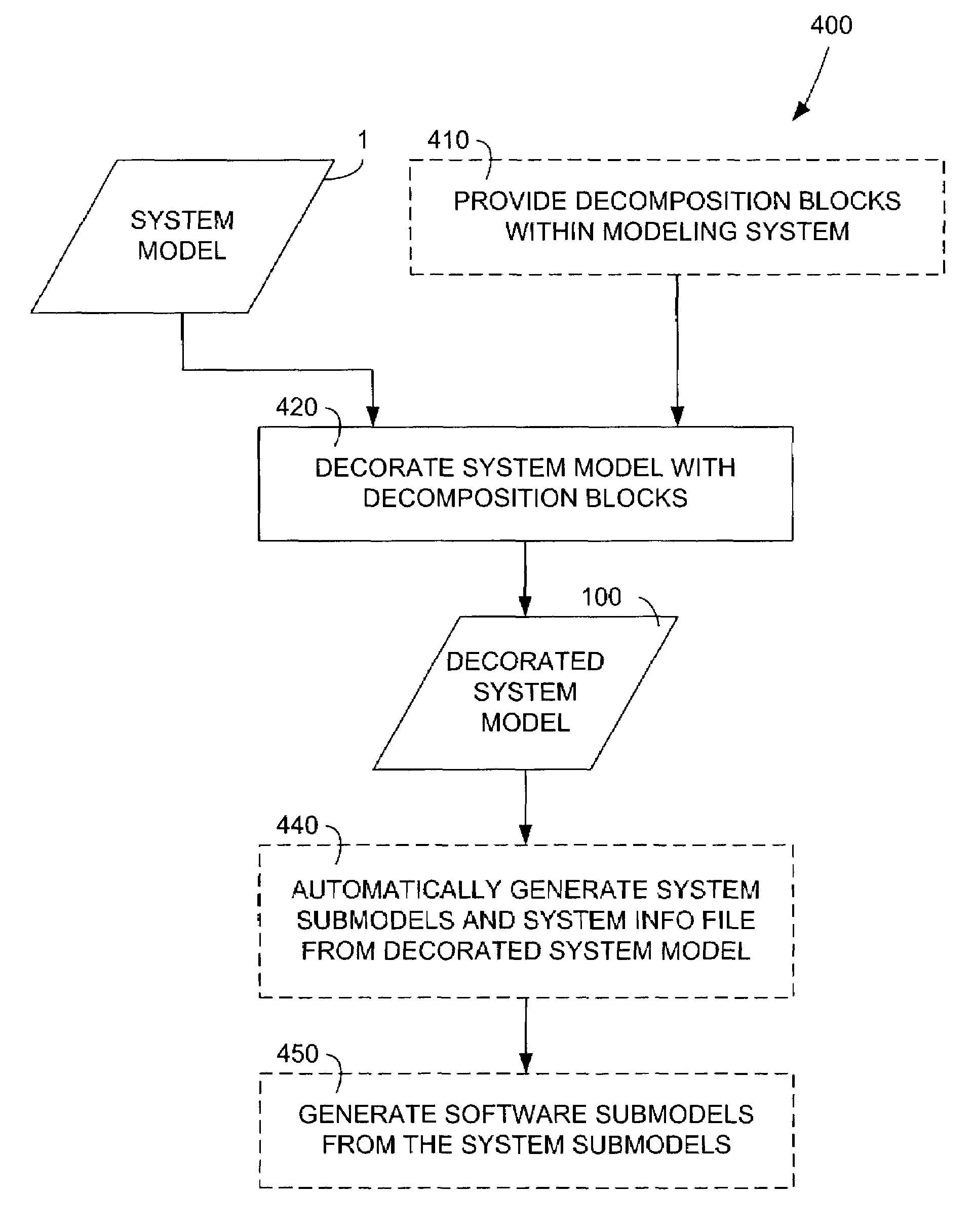
[0024]FIG. 4 shows an integra...


PUM


Abstract

A method for automatically decomposing a dynamic system model into separate submodels for ultimate execution on diverse target platforms is provided. Embodiments of the invention provide a way for a system designer to indicate which portions of a previously-specified system model are to become submodels. Optionally, the designer may also indicate the associated target platform for the execution of each submodel. A system submodel for each portion designated by the designer is generated, keeping all critical system-level information consistent throughout the entire system model. Each of these system submodels may then be employed to generate a software version of each system submodel. Each software submodel may then be transferred to its specified target platform and executed in cooperation with the other software submodels to effect an overall system simulation executing across the associated target platforms. Alternately, one or more system submodels may be replaced by the actual components of the dynamic system represented by those system submodels.

Description

BACKGROUND OF THE INVENTION[0001]Dynamic systems, which are human-devised systems that respond in some beneficial way to changing conditions within their environment, represent a significant challenge to the designers of such systems due to the myriad and diverse conditions such systems must be capable of handling effectively. For example, electrical and electronic circuits, which represent but one type of dynamic system, often must react to ever-changing input signals by providing output signals based on the input signals, thereby causing some favorable action in the environment in which, the system operates. Electrical and electronic circuits are utilized to great advantage in a plethora of applications, from everyday consumer appliances, such as microwave ovens and personal computers, to high-tech military weaponry. Additionally, dynamic systems also include any type of software written to perform a specific, useful function. Furthermore, dynamic systems may include, but are not ...

Claims


Application Information

Patent Timeline
Patent Type & Authority Patents(United States)
IPC IPC(8): G06F9/44G06F17/50
CPCG06F17/5009G06F30/20
Inventor ALLEN, RICHARD CRAIGCOVERSTONE, RANDY A
Owner AGILENT TECH INC
Why Eureka
Try Eureka