
Rheometer

a rheometer and rheometer technology, applied in the field of rheometers, can solve the problem of confined effect of intermittent external noise sources, and achieve the effect of accurate measurements

Inactive Publication Date: 2007-03-27
GBC SCI EQUIP
View PDF6 Cites 2 Cited by
  • Summary
  • Abstract
  • Description
  • Claims
  • Application Information

AI Technical Summary

Benefits of technology

"The present invention provides a rheometer that can make accurate measurements with small amounts of sample. The invention includes a driver for applying an alternating movement to a sample, a force measuring device for providing a force signal indicative of the reaction force exerted by the sample, a displacement measuring device for measuring the alternating movement of the sample, and a processor for determining the rheological property of the sample. The invention also includes a signal generator for supplying a frequency sweep signal to the driver, which ensures that harmonics are distributed in a well-defined way and can be corrected for in the data processing. The invention further includes a sample support for holding the sample, a displacement transducer for measuring the displacement of the sample, and a load cell for measuring the force on the sample. The invention also provides a method for determining the rheological property of a sample by applying an alternating movement to the sample, measuring the force signal and the movement signal, and processing them to determine the rheological property."

Problems solved by technology

Furthermore, the effect of intermittent external noise sources is confined to the frequencies during which they occurred, rather than being spread across the whole spectrum.

Method used


Image

  • Rheometer
  • Rheometer
  • Rheometer

Examples


Embodiment Construction

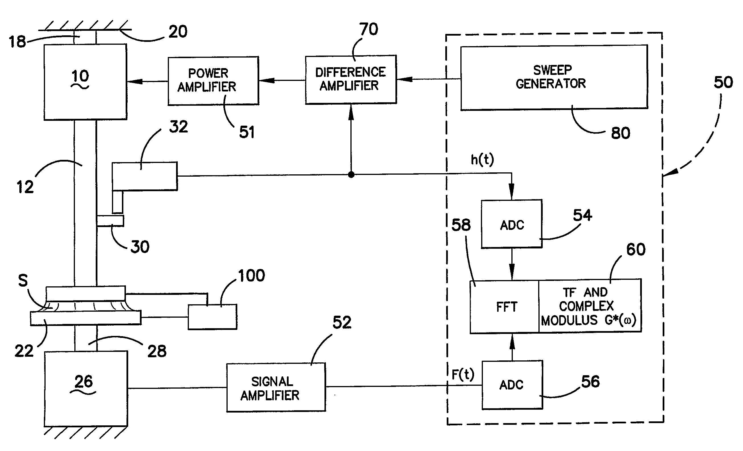
[0114]With reference to FIG. 1, a rheometer according to the preferred embodiment of the invention is shown which has a driver 10 which is preferably formed from a terfenite material and electromagnets for supplying a magnetic field to the terfenite material. Most preferably the terfenite material is in the form of rods which, when the magnetic field is applied, grow in the magnetic field. Thus, by applying an alternating magnetic field to the terfenite rods, the movement of the terfenite rods causes a vibration which creates an alternating movement of the driver 10. Such drivers are known per se and therefore need not be defined in further detail.

[0115]The driver 10 has a connecting rod 12 formed from metal which can vibrate with the driver 10, and the rod 12 is connected to top plate 14 of a sample support station 16. The driver 10 may be supported by support 18 to a casing 20 or housing of the rheometer.

[0116]The sample station 16 includes a bottom plate 22 and a space 24 is prov...


PUM

PropertyMeasurementUnit
thicknessaaaaaaaaaa
thickaaaaaaaaaa
rheological propertyaaaaaaaaaa

Abstract

A rheometer and method of making rheological measurements is disclosed, in which a sample is supported between plates and an alternating movement is applied by a driver, support rod and plate. Force and displacement measurements are taken and the property determined from those measurements. The vibrating signal which is applied is in the form of a frequency sweep signal having a monotonic group delay function. The top plate is provided with a surface which causes a meniscus to form up a side edge of the plate to reduce the spring nature of the sample when the movement is supplied to the sample, and a supporting rod which supports the top plate is preferably formed from a material having a low coefficient of thermal expansion so that the gap between the plates is maintained substantially constant if the sample is heated to take measurements at different temperatures.

Description

FIELD OF THE INVENTION[0001]This invention relates to a rheometer and, in particular, to a rheometer which can measure the complex viscosity and complex modulus of small volumes of fluids, as well as other rheological properties of materials such as elasticity.BACKGROUND ART[0002]Most conventional rheometers which measure viscosity, often simply referred to as viscometers, cannot be used for measuring viscosities of non-Newtonian samples. Furthermore, most conventional viscometers need large amounts of sample in order to enable measurements to be made. This is therefore a significant disadvantage, because in many cases, only very small amounts of sample are available for analysis.SUMMARY OF THE INVENTION[0003]The object of the present invention is to provide a rheometer which can provide measurements with only small amounts of sample and which can also make accurate measurements.[0004]The invention provides a rheometer for determining a rheological property of a sample, comprising:[...

Claims


Application Information

Patent Timeline
Patent Type & Authority Patents(United States)
IPC IPC(8): G01N11/10G01N3/32G01N11/00G01N11/16G01N33/44
CPCG01N11/16G01N2011/0013G01N33/442G01N3/32G01N11/00
Inventor GREY, RONALD GARWOODCONDICK, GEOFFREY MARKSVENDSEN, DEAN
Owner GBC SCI EQUIP
Learn More