Position sensor system and vehicle seat provided with the position sensor system
- Summary
- Abstract
- Description
- Claims
- Application Information
AI Technical Summary
Benefits of technology
Problems solved by technology
Method used
Image
Examples
first embodiment
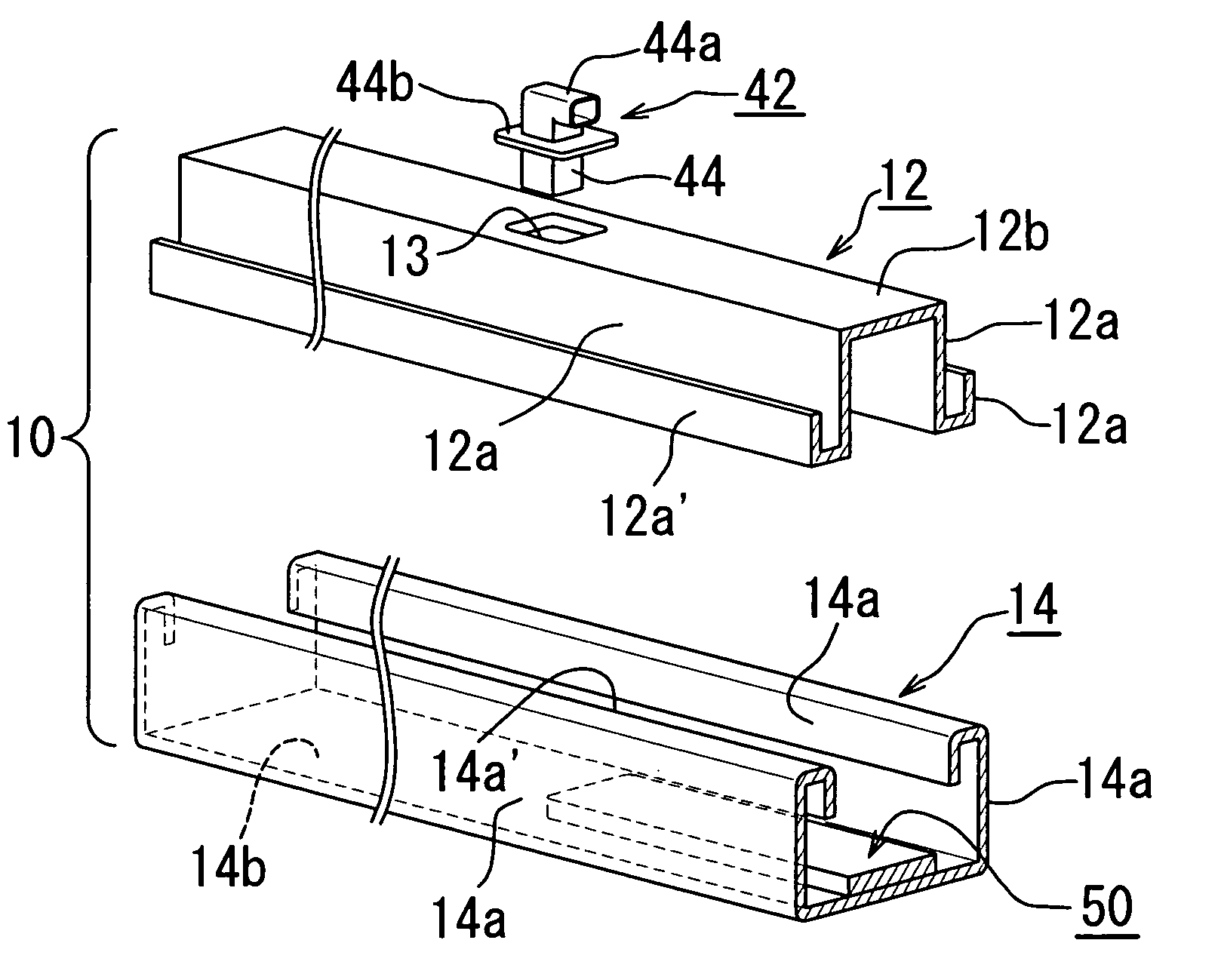
[0082]Referring to FIG. 4, there is illustrated the slide rail means 10 (only one slide rail means 10 is shown in FIG. 4) and the position sensor system 20 according to the present invention. The pair of the slide rail means 10 comprise upper rail members 12 attached to lower portions of the seat, and lower rail members 14 mounted to the vehicle floor. The upper rail members 12 attached to the seat are slidably supported through rollers (not shown) to the lower rail members 14, whereby the seat can be moved forward and rearward along the lower rail members 14. The position sensor system 20 is mounted within at least one of the pair of the slide rail means 10 and comprises a position sensor unit 22 and an elongated magnetic shielding plate 23 of a substantially L-shape in cross-section.
[0083]Each of the upper rail members 12 comprises a longitudinal body of a substantially inverted U-shape in cross-section. The longitudinal body of the upper rail member 12 comprises a pair of spaced ...
second embodiment
[0096]The position sensor system 30 according to the present invention comprises a high-frequency oscillating-type proximity sensor 32, and metallic and nonmetallic portions 34, 36 which serve as objects to be sensed by the proximity sensor 32 and are provided in the bottom plate section 14b of the lower rail member 14. In this embodiment, the lower rail member 14 is made of metal. The nonmetallic portion 36 is provided in a region of the bottom plate section 14b which is more rear than the approximately middle portion of the longitudinal direction of the bottom plate section 14b. Thus, a portion of the bottom plate section 14b at which the nonmetallic portion 36 is not provided serves as the metallic portion 34 to be sensed by the proximity sensor 32. The nonmetallic portion 36 may comprise a hole or slit.
[0097]The proximity sensor 32 includes a box-like housing 32a having a high-frequency oscillating section (not shown) housed therein, the high-frequency oscillating section includ...
third embodiment
[0104]In the present invention, when the magnetic sensor 42 is withdrawn from the strip-shaped magnet 50, the magnetic sensor 42 generates a first electric signal representative of the seat being in the forward position, and transmits the first signal to the controller. When the magnetic sensor 42 is operatively opposed to the magnet 50 and responds to a magnetic field created by the magnet 50, the magnetic sensor 42 generates a second electric signal representative of the seat being in the rearward position, and transmits the second signal to the controller. The controller controls the passenger restraint device so as to cause the deployment of the passenger restraint device to be expedited, according to the first electric signal, and controls the passenger restraint device so as to cause the deployment of the passenger restraint device to be delayed, according to the second electric signal.
[0105]Like the position sensor system 20 according to the first embodiment of the present in...
PUM
 Abstract
Description
Claims
Application Information
 - R&D
- Intellectual Property
- Life Sciences
- Materials
- Tech Scout
- Unparalleled Data Quality
- Higher Quality Content
- 60% Fewer Hallucinations
Browse by: Latest US Patents, China's latest patents, Technical Efficacy Thesaurus, Application Domain, Technology Topic, Popular Technical Reports.
© 2025 PatSnap. All rights reserved.Legal|Privacy policy|Modern Slavery Act Transparency Statement|Sitemap|About US| Contact US: help@patsnap.com


