
Apparatus and method for producing article

Active Publication Date: 2007-03-27
ZUIKO CORP
View PDF21 Cites 86 Cited by
  • Summary
  • Abstract
  • Description
  • Claims
  • Application Information

AI Technical Summary

Benefits of technology

[0006]It is therefore an object of the present invention to provide an apparatus for producing an article having an elastic member that is capable of transferring an elastic member onto a web while preventing point-to-point variations in the extension of the elastic member.
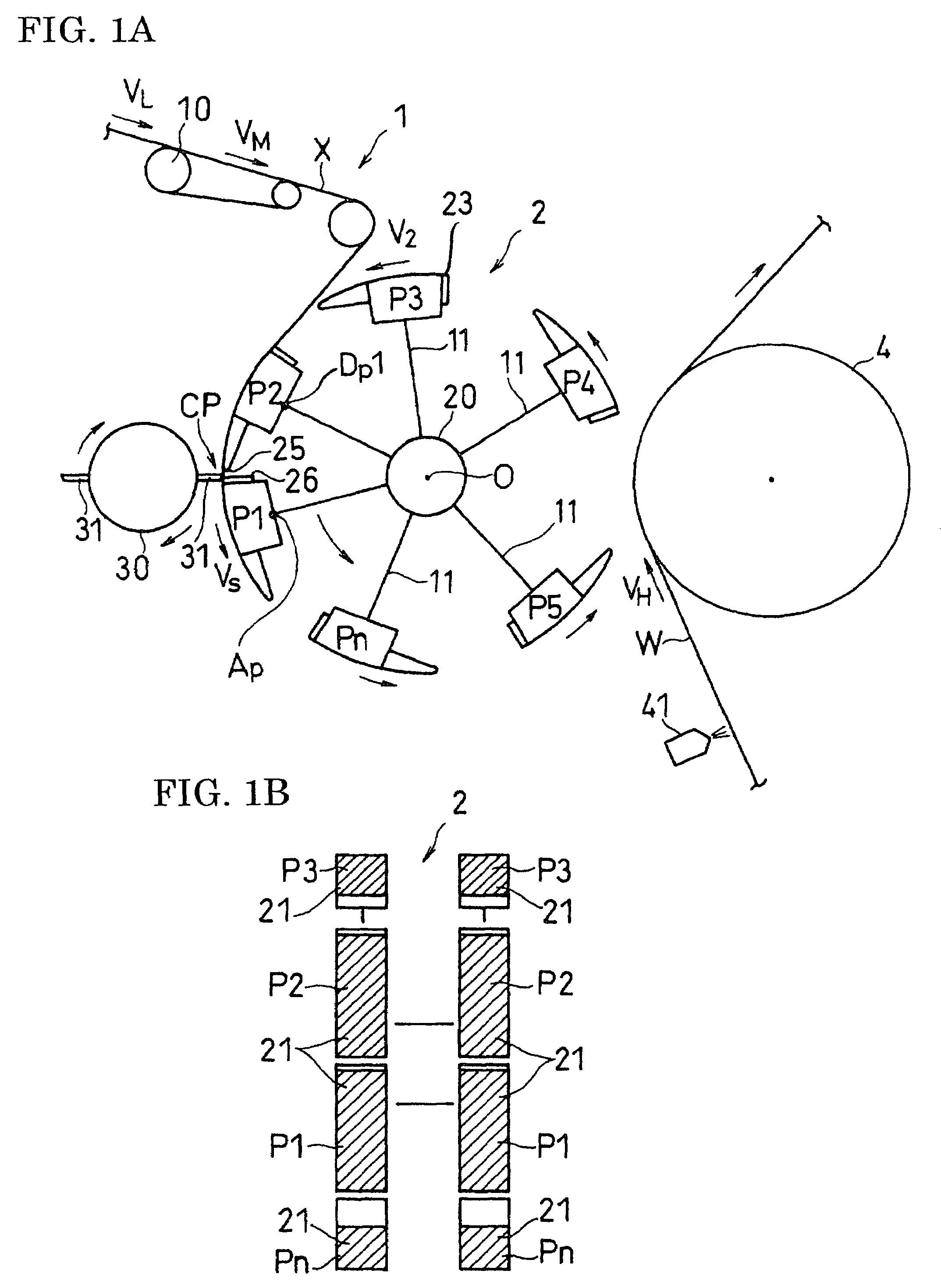
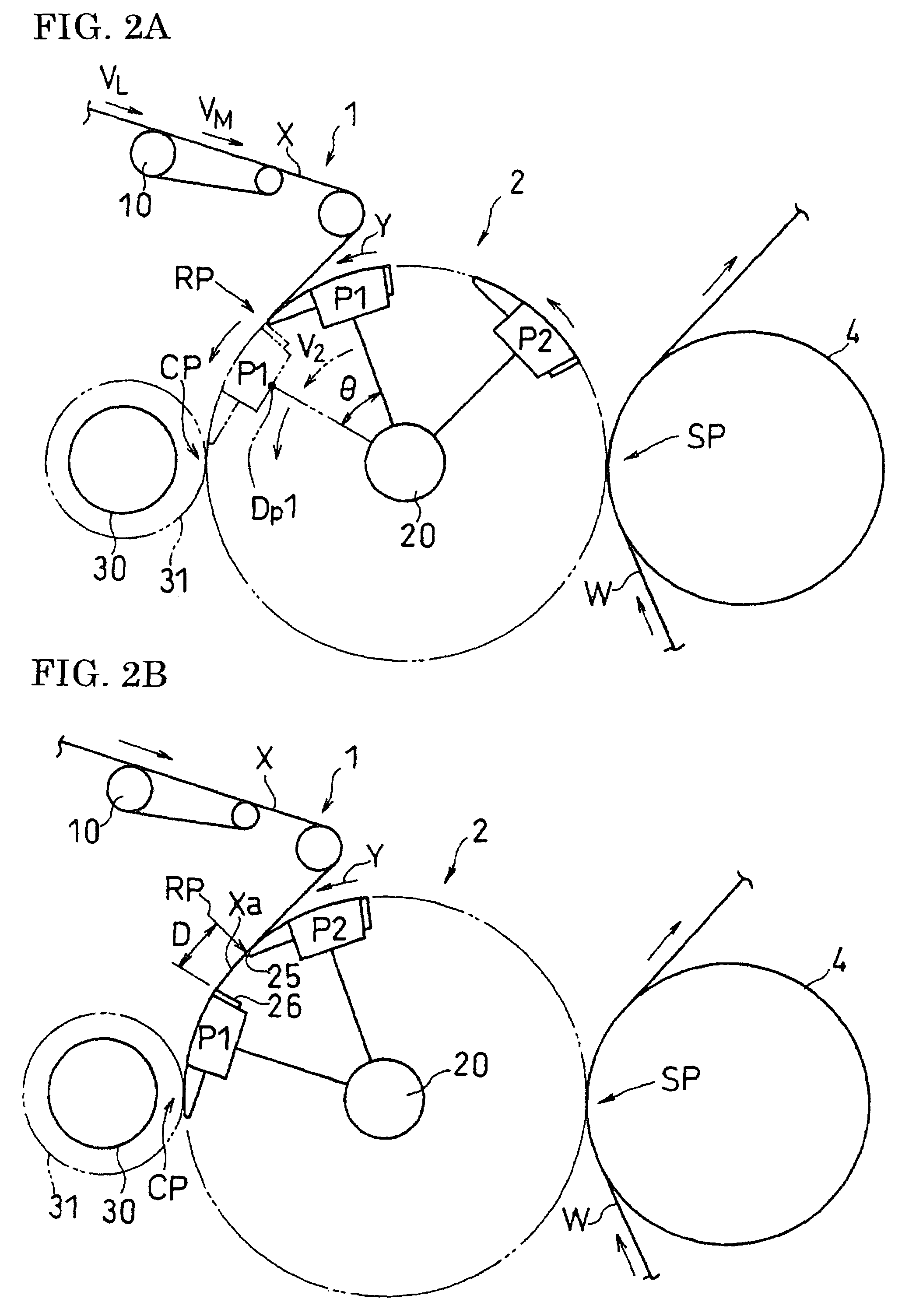
[0010]The circumferential velocity V2 of the pad may be set to a value that is generally equal to the medium velocity VM. In this way, the extension of the elastic member does not change while the elastic member is carried from the stretcher to the carrier, thereby further reducing the variations in the extension of the elastic member. The circumferential velocity of one pad of the carrier may be kept at a generally constant high velocity Vh from when the pad starts handing over the elastic member onto the web until the completion of the hand-over operation. In this way, the extension of the elastic member does not change while the elastic member is moved from the carrier onto the web, thereby further reducing the variations in the extension of the elastic member.
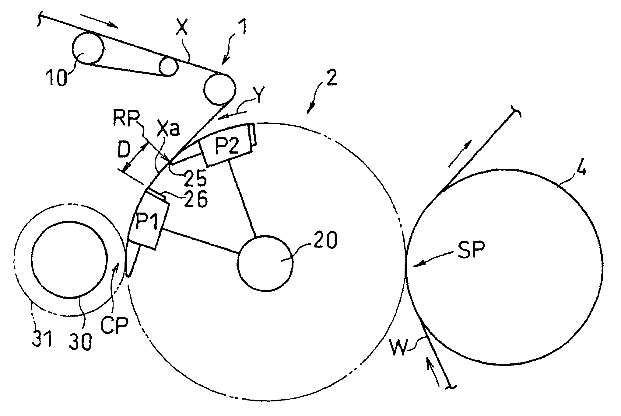
[0011]In the present invention, after the preceding pad completely picks up the elastic member at the velocity V2, the circumferential velocity of the preceding pad may decrease so that the front end of the following pad comes close to, or into contact with, the rear end of the preceding pad, in which state the elastic member may be cut off by a cutter into two pieces corresponding to the two pads. In this way, the elastic member can be cut off at a position between the pads, thereby reducing the point-to-point variations in the extension of the elastic member on each pad.

Problems solved by technology

The extension being significantly non-uniform may result in poor wearability and leakage of bodily fluids.

Method used


Image

  • Apparatus and method for producing article
  • Apparatus and method for producing article
  • Apparatus and method for producing article

Examples


Embodiment Construction

[0022]An embodiment of the present invention will now be described with reference to the drawings.

[0023]FIG. 1A and FIG. 1B illustrate a production apparatus of the present invention. The production apparatus illustrated in FIG. 1A and FIG. 1B includes a stretcher 1, a carrier 2 and a disposing station 4.

[0024]The stretcher 1 receives an elastic member X, stretches the elastic member X to a predetermined extension, and outputs the stretched elastic member X. The stretcher 1 may include a belt conveyer 10 capable of carrying the elastic member X at a medium velocity VM. The elastic member X is carried from upstream of the belt conveyer 10 at a low velocity VL lower than the medium velocity VM, and is accelerated to the medium velocity VM by the belt conveyer 10. Thus, the elastic member X is stretched by the velocity difference.

[0025]The carrier 2 includes a plurality of pads P1 for receiving the stretched elastic member X and a cutter 31 for cutting off the elastic member X in a pre...


PUM

PropertyMeasurementUnit
Forceaaaaaaaaaa
Distanceaaaaaaaaaa
Velocityaaaaaaaaaa

Abstract

An apparatus for producing an article having an elastic member, comprises: a stretcher for receiving the elastic member at a low velocity VL and outputting the elastic member at a medium velocity VM; a carrier including a first pad and a second pad for picking up the elastic member from the stretcher, and a cutter for cutting off the elastic member while carrying the elastic member; and a station for carrying a web at a high velocity Vh and disposing the cut-off elastic member from a pad onto the web. When the elastic member striding over the first pad and the second pad is cut off, an interval between the first pad and the second pad is shortened so as to reduce a shrinking force of a portion of the elastic member between the first pad and the second pad.

Description

BACKGROUND OF THE INVENTION[0001]1. Field of the Invention[0002]The present invention relates to an apparatus and method for producing an article having an elastic member, such as a sanitary napkin, a disposable diaper, and a disposable pants-type diaper.[0003]2. Description of the Related Art[0004]In a disposable worn article, an elastic member is placed on the sheet surface to form gathers so that the article fits to various parts of the body of the wearer. The elastic member is preferably placed on the sheet surface at as uniform an extension as possible. The extension being significantly non-uniform may result in poor wearability and leakage of bodily fluids.[0005]Conventional apparatuses and methods for producing a worn article fail to ensure a uniformity of the extension of the elastic member (see, for example, Japanese Laid-Open Patent Publication No. 8-197498, and Japanese National Phase PCT Laid-Open Publication Nos. 8-511707, 11-503060 and 11-504228).SUMMARY OF THE INVENTI...

Claims


Application Information

Patent Timeline
IPC IPC(8): A61F13/15A61F13/472A61F13/49B65H35/04B65H39/14
CPCA61F13/15593B65H35/08B65H39/14B65H2406/3454
Inventor SATOH, HITOSHI
Owner ZUIKO CORP
Learn More