Sensing apparatus and method

a technology of sensing apparatus and position measurement, which is applied in the direction of washing apparatus, liquid/fluent solid measurement, coil, etc., can solve the problems of inconvenient application, limited position measurement resolution, and incorrect readings

Inactive Publication Date: 2007-03-27
TT ELECTRONICS TECH
View PDF52 Cites 34 Cited by
  • Summary
  • Abstract
  • Description
  • Claims
  • Application Information

AI Technical Summary

Benefits of technology

[0009]In an embodiment, the conductive tracks of the magnetic field generator are associated with a transmit aerial, the detector comprises a receive aerial, and the sensor element forms an intermediate coupling element between the transmit aerial and the receive aerial. The electromagnetic coupling between the transmit aerial and the receive aerial varies with the position of the sensor element, enabling the detector to detect the position of the sensor element from a signal induced in the receive aerial.

Problems solved by technology

However, a disadvantage of capacitive sensors is that exposure to liquids such as water can lead to incorrect readings.
For the position sensor described in WO 03 / 038379, using conventional techniques it is difficult to deposit the two excitation windings so that the period of the associated sine and cosine functions is less than a few centimeters, and this limits the available resolution for position measurement.
Further, the position sensor described in WO 03 / 038379 measures movement of a sensor element along a measurement path parallel to the plane of a planar member, and therefore is not well suited to applications in which movement of a sensor element transverse (i.e. crossing) to the plane of a planar member, for example a fascia panel, is to be measured.

Method used


Image

  • Sensing apparatus and method
  • Sensing apparatus and method
  • Sensing apparatus and method

Examples


first embodiment

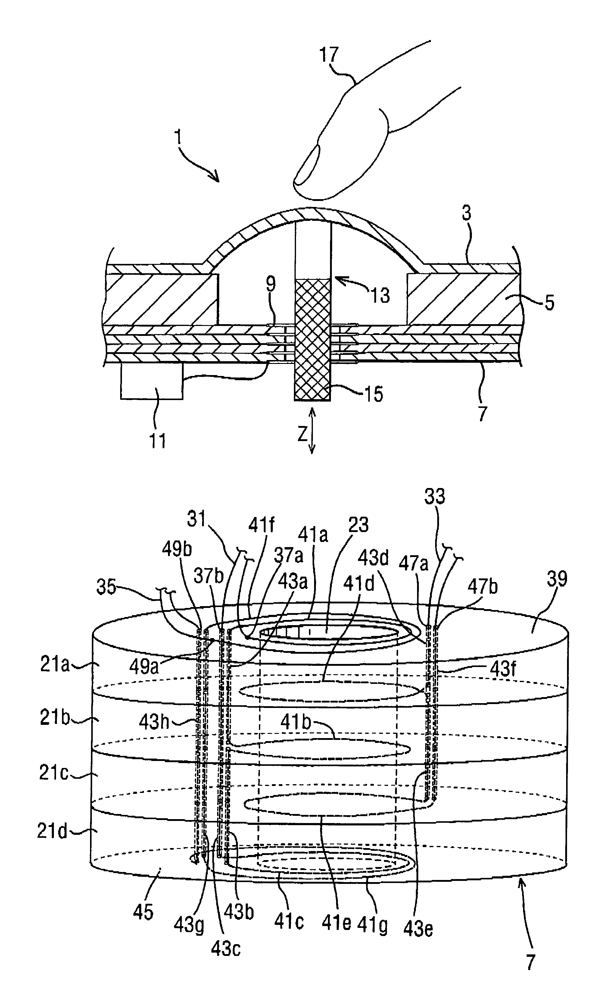
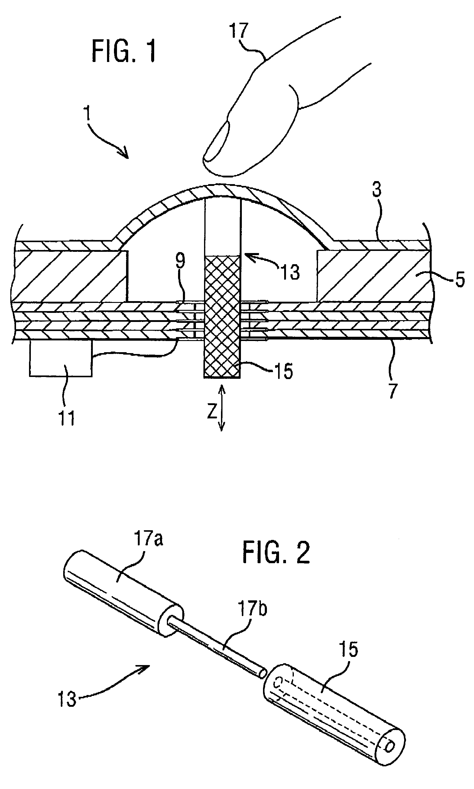
[0028]FIG. 1 shows a push button assembly 1 in which a resiliently flexible membrane 3 is mounted to one side of a planar substrate 5, which in this embodiment is an ABS fascia panel. A hole is formed through the planar substrate 5 and the membrane 3 is arranged to arc above the hole. A multi-layer printed circuit board (PCB) 7 is mounted to the face of the substrate 5 away from the flexible membrane 3, and the PCB 7 has an aperture therethrough which is aligned with the centre of the hole through the planar substrate 5.

[0029]Conductive tracks 9 deposited on the layers of the multi-layer PCB 7 form a transmit aerial and a receive aerial as will be described in more detail hereafter. The conductive tracks 9 are connected to signal generation and processing circuitry 11 which is mounted to the face of the multi-layer PCB 7 away from the planar substrate S. The signal generation and processing circuitry 11 applies excitation signals to the transmit aerial, which cause the transmit aeri...

second embodiment

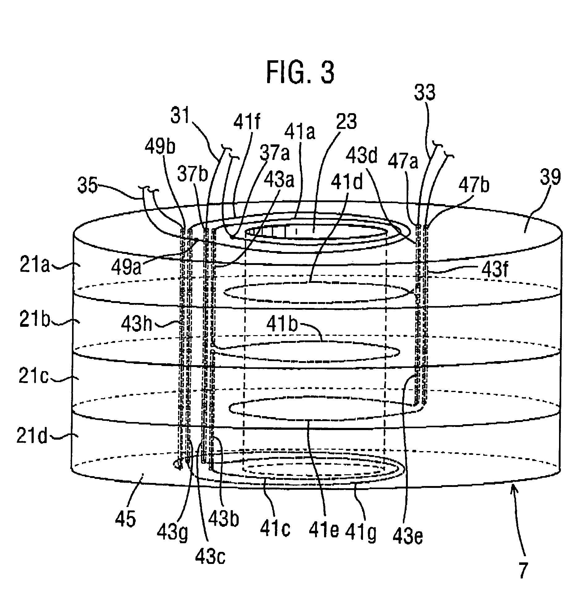
[0046]In the first embodiment, by depositing conductive tracks between the layers of, and on the end surfaces of, a multi-layer PCB 7 which is parallel with a planar substrate 5, the sinusoidal variation along a measurement direction z of the magnetic field strength components perpendicular to the planar substrate 5 associated with the cosine winding 31 and the sine winding 33 is achieved.

[0047]A second embodiment will now be described with reference to FIGS. 6 to 9 in which the five-layer PCB 7 of the first embodiment is replaced by a two-layer PCB 91, with the sinusoidal variation in magnetic field strength component perpendicular to the planar substrate 5 being achieved by a sine winding and a cosine winding formed by conductive tracks which are deposited on a first surface 93 and a second surface 95 which are on either side of the single substrate layer 91, and by through-plated via holes passing through the single substrate layer 91. The two-layer PCB 91 has an aperture 97 thro...

third embodiment

[0060]The first and second embodiments describe push button assemblies. The invention could, however, be applied to other types of man-machine interface. A third embodiment of the invention will now be described with reference to FIG. 10 in which the inductive sensor of the first embodiment is incorporated in a rotary switch assembly 171.

[0061]As shown in FIG. 10, the rotary switch assembly 171 has a switch head 173 which is mounted to an elongate cylindrical shaft 175, which in turn is rotatably mounted to in a recess in a fascia panel 177. In particular, a flange 179 is provided at the end of the shaft 175 inserted in the recess. The flange 179 engages a flange 181 provided on the inner surface of the recess to allow rotational movement of the shaft 175 about its longitudinal axis but prevent axial movement of the shaft 175 along its longitudinal axis.

[0062]The switch head 173 includes a sleeve portion 181 into which the shaft 175 is mounted, and which is partially inserted within...


PUM


Abstract

There is described a position sensor comprising at least one planar substrate having formed thereon a magnetic field generator which comprises conductive tracks formed on at least two planes defined by the at least one planar substrate. An intermediate coupling element is operable to move relative to the at least one planar substrate along a measurement direction transverse to the planar substrate, the detector detects the position of the intermediate coupling element in a magnetic field generated by the magnetic field generator. The position sensor has particular application in man-machine interfaces such as push buttons and rotary switches.

Description

CROSS-REFERENCE TO RELATED APPLICATIONS[0001]This application is a continuation-in-part application of International Application No. PCT / GB02 / 01707 filed 12 Apr. 2002 designating the United States and entitled “Sensing Apparatus and Method”, and also a continuation-in-part application of International Application No. PCT / GB2003 / 003718 filed 27 Aug. 2003 designating the United States and entitled “Sensing Apparatus and Method”. The whole contents of International Patent Application Nos PCT / GB02 / 01707 and PCT / GB2003 / 003718 are hereby incorporated in this application by reference.FIELD OF THE INVENTION[0002]This invention relates to a method of sensing the position or the speed of an object, and an apparatus therefor. The invention has particular, but not exclusive, relevance to a man-machine interface which is mounted on a fascia panel or the like.BACKGROUND OF THE INVENTION[0003]There are numerous examples of devices which have a man-machine interface mounted on a fascia panel. For e...

Claims


Application Information

Patent Timeline
Patent Type & Authority Patents(United States)
IPC IPC(8): H01H9/00D06F39/00D06F39/08G01D5/20G01F23/16
CPCD06F39/003G01F23/164G01D5/2073D06F39/087G01D5/206
Inventor SILLS, COLIN S.JAMES, DAVID A.
Owner TT ELECTRONICS TECH
Why Eureka
Try Eureka