Self-pinned spin valve sensor with stress modification layers for reducing the likelihood of amplitude flip

a spin valve sensor and stress modification technology, applied in the direction of assembling head elements, instruments, data recording, etc., can solve the problems of pinning field to flip its orientation, corrupt data, etc., and achieve the effect of reducing the likelihood

Inactive Publication Date: 2007-03-27
WESTERN DIGITAL TECH INC
View PDF4 Cites 19 Cited by
  • Summary
  • Abstract
  • Description
  • Claims
  • Application Information

AI Technical Summary

Benefits of technology

[0013]A spin valve sensor of the self-pinned type includes one or more compressive stress modification layers for substantially reducing the likelihood that the pinning field will flip its direction. The spin valve sensor includes a capping layer formed over a spin valve structure which includes a free layer, an antiparallel (AP) self-pinned layer structure, and a spacer layer in between the free layer and the AP self-pinned layer structure. A compressive stress modification layer is formed above or below the capping layer, adjacent the AP self-pinned layer structure, or both. Preferably, the compressive stress modification layer is made of ruthenium (Ru) or other suitable material.

Problems solved by technology

One of the key challenges for self-pinned spin valves, however, has been to improve the pinning field against “flipping”.
However, when an undesirable head-to-disk interaction occurs (due to defects, asperities, bumps, etc.), the sensor experiences compressive or tensile stress which causes the pinning field to flip its orientation.
This causes the amplitude of the readback signal to flip (hence the terminology “amplitude flip”), which results in corrupt data.

Method used


Image

  • Self-pinned spin valve sensor with stress modification layers for reducing the likelihood of amplitude flip
  • Self-pinned spin valve sensor with stress modification layers for reducing the likelihood of amplitude flip
  • Self-pinned spin valve sensor with stress modification layers for reducing the likelihood of amplitude flip

Examples


first embodiment

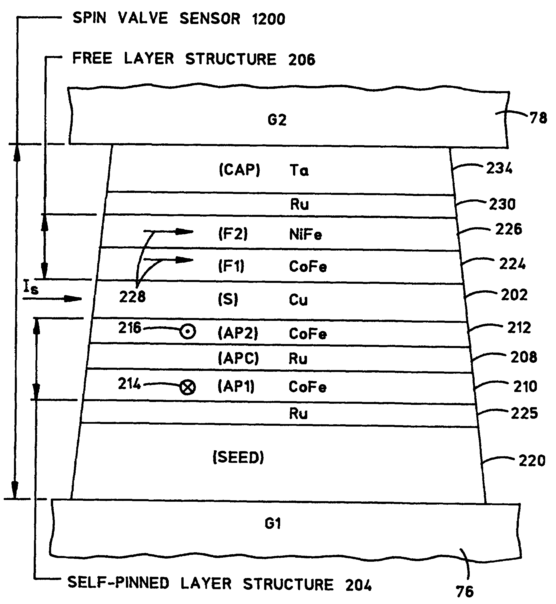
[0040]FIG. 11 is an ABS illustration of a multi-layer structure of a spin valve sensor 1200 of the self-pinned type with compressive stress modification layers for reducing the likelihood that the pinning field will flip its direction. Spin valve sensor 1100 of FIG. 11 is similar to the spin valve sensor of FIG. 10 except that it includes compressive stress modification layers 225 and 230.

[0041]Compressive stress modification layer 225 is formed adjacent AP self-pinned layer structure 204. More particularly, compressive stress modification layer 225 is formed directly between first AP pinned layer 210 and seed layer 220. The addition of compressive stress modification layer 225 modifies the intrinsic compressive stress within spin valve sensor 1100. Since the self-pinning effect is a result of negative anisotropy which is based on positive magnetostriction and compressive stress, any external compressive stresses have a diminished effect on the pinning field. Therefore, compressive ...

second embodiment

[0044]FIG. 12 is an ABS illustration of a multi-layer structure of a spin valve sensor 1200 of the self-pinned type with compressive stress modification layers for reducing the likelihood that the pinning field will flip its direction. Spin valve sensor 1200 is similar to the spin valve sensor of FIG. 11 except that compressive stress modification layer 230 of FIG. 12 is formed between capping layer 234 and free layer structure 206 instead of being formed on top of capping layer 234. As with compressive stress modification layer 230 of FIG. 11, compressive stress modification layer 230 of FIG. 12 modifies the intrinsic compressive stress within spin valve sensor 1200 and therefore reduces the likelihood that the pinning field will flip its direction. Although the structure of spin valve sensor 1200 of FIG. 12 may be well-suited for some applications, spin valve sensor 1100 of FIG. 11 is preferred over that of FIG. 12 since, in some GMR designs, the presence of ruthenium next to the ...

third embodiment

[0045]FIG. 13 is an ABS illustration of a multi-layer structure of a spin valve sensor 1300 of the self-pinned type having a compressive stress modification layer for reducing the likelihood that the pinning field will flip its direction. Spin valve sensor 1300 is similar to the spin valve sensor of FIG. 11 except that compressive stress modification layer 225 of FIG. 11 is removed. Nevertheless, compressive stress modification layer 230 of FIG. 13 formed over capping layer 234 in itself modifies the intrinsic compressive stress within spin valve sensor 1300 and therefore reduces the likelihood that the pinning field will flip its direction.


PUM

PropertyMeasurementUnit
thickaaaaaaaaaa
Thicknessesaaaaaaaaaa

Abstract

A spin valve (SV) sensor of the self-pinned type includes one or more compressive stress modification layers for reducing the likelihood that the pinning field will flip its direction. The spin valve sensor includes a capping layer formed over a spin valve structure which includes a free layer, an antiparallel (AP) self-pinned layer structure, and a spacer layer in between the free layer and the AP self-pinned layer structure. A compressive stress modification layer is formed above or below the capping layer, adjacent the AP self-pinned layer structure, or both. Preferably, the compressive stress modification layer is made of ruthenium (Ru) or other suitable material.

Description

BACKGROUND OF THE INVENTION[0001]1. Field of the Invention[0002]This invention relates generally to spin valve sensors of magnetic heads, and more particularly to the utilization of one or more stress modification layers in a spin valve sensor of the self-pinned type for reducing the likelihood that the pinning field will flip its direction.[0003]2. Description of the Related Art[0004]Computers often include auxiliary memory storage devices having media on which data can be written and from which data can be read for later use. A direct access storage device (e.g. a disk drive) incorporating rotating magnetic disks are commonly used for storing data in magnetic form on the disk surfaces. Data is recorded on concentric, radially spaced tracks on the disk surfaces. Magnetic heads including read sensors are then used to read data from the tracks on the disk surfaces.[0005]In high capacity disk drives, magnetoresistive read (MR) sensors, commonly referred to as MR heads, are the prevail...

Claims


Application Information

Patent Timeline
Patent Type & Authority Patents(United States)
IPC IPC(8): G11B5/39G11B5/127G11B5/33
CPCG11B5/33G11B5/1272
Inventor FOX, CIARAN AVRAMGILL, HARDAYAL SINGHKASIRAJ, PRAKASHLEE, WEN-YAUNGPINARBASI, MUSTAFA MICHAEL
Owner WESTERN DIGITAL TECH INC
Why Eureka
Try Eureka