Capacitor anode assembly

a technology of capacitors and anodes, which is applied in the field of electrolytic capacitors, can solve the problems of insufficient dielectric voltage of the area of anodes, and increasing the size of the anodes

Active Publication Date: 2007-03-27
PACESETTER INC
View PDF30 Cites 33 Cited by
  • Summary
  • Abstract
  • Description
  • Claims
  • Application Information

AI Technical Summary

Problems solved by technology

Increasing the size of the anodes creates another problem, however, as it is still necessary to electrically insulate the anode plates from the case, which typically is grounded to the cathode assembly.
This solution has proven to be problematic though, as the adhesive tape can interfere with the aging process of the anode edges.
However, adhesive covering the edge of the anodes can prevent fill electrolyte (the aging medium) from reaching the raw aluminum surfaces, resulting in areas of the anodes that have insufficient dielectric voltage during fast charging and discharging.
In ICDs used for pulse discharge applications, during the charging process, this can result in abnormally long charge times, due to the fact that charging energy is consumed to age these newly exposed areas in order to sufficiently store charge.
These solutions all present drawbacks either to manufacturability, or result in a decrease in energy density due to decreased anode volume.

Method used


Image

  • Capacitor anode assembly
  • Capacitor anode assembly
  • Capacitor anode assembly

Examples


Embodiment Construction

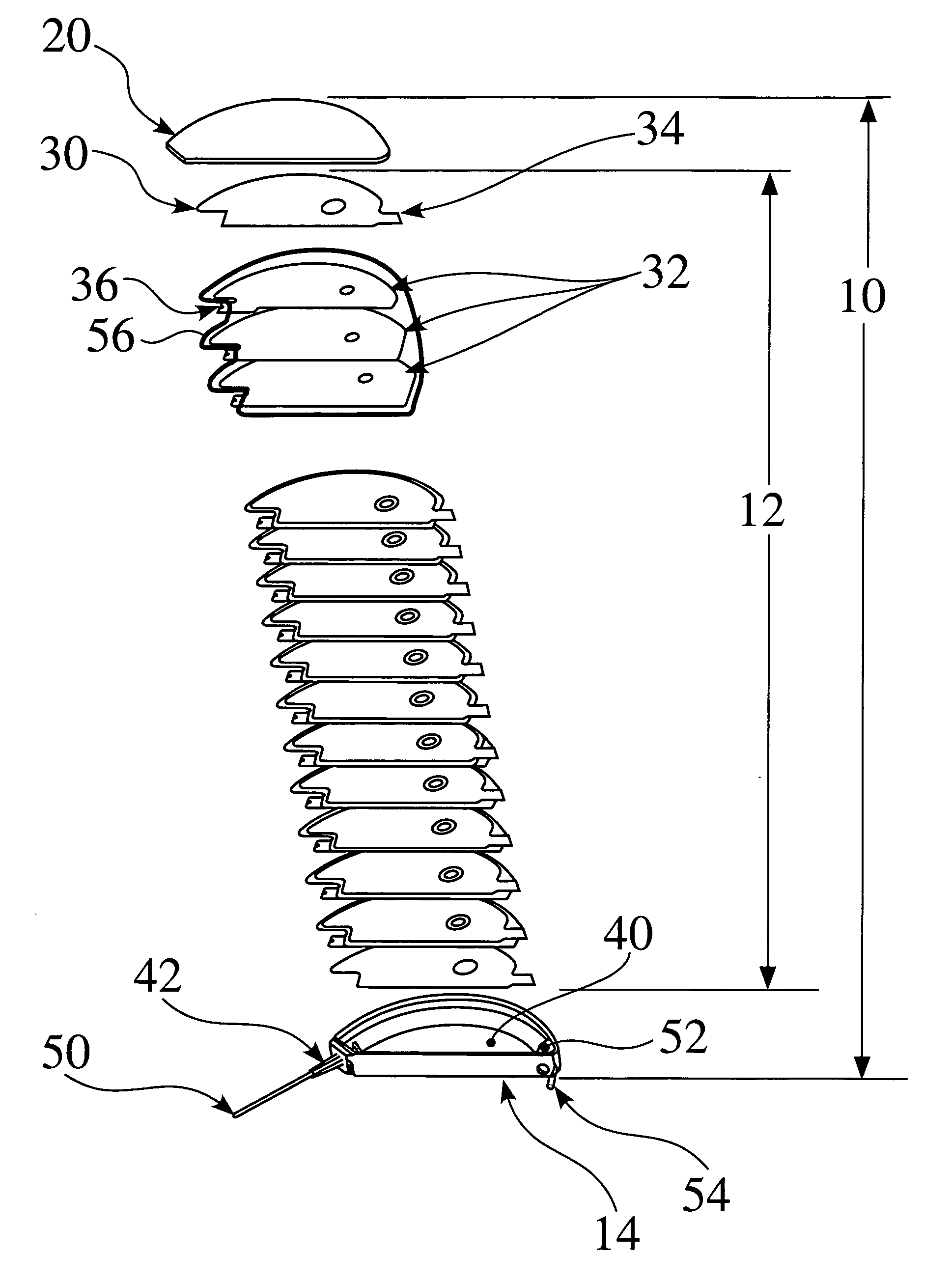
[0034]The present invention provides for encapsulated anode assemblies and encapsulated or enclosed stacked capacitor configurations for use within an electrolytic capacitor. The present invention also provides electrolytic capacitors including the encapsulated anode assemblies and encapsulated or enclosed stacked capacitor configurations of the present invention.

[0035]Preferred embodiments of the present invention are now described. While specific configurations and arrangements are discussed, it should be understood that this is done for illustrative purposes only. A person skilled in the relevant art will recognize that other configurations and arrangements can be used without departing from the spirit and scope of the invention. It will also be apparent to a person skilled in the relevant art that this invention can be employed in a variety of other devices and applications.

[0036]The capacitance value of a capacitor (C) depends on the area (A) of the plates on which the charge a...


PUM

PropertyMeasurementUnit
voltageaaaaaaaaaa
voltageaaaaaaaaaa
DC current densityaaaaaaaaaa

Abstract

According the present invention, anode foils are encapsulated in separator material so as to insulate them from the metal housing of an electrolytic capacitor. The present invention also provides for enclosed capacitor configurations for use in stacked capacitor configurations. Preferably, heat-sealable polymeric materials are used as separator materials to encapsulate or enclose the anode assemblies and capacitor configurations. The encapsulated anode assemblies and capacitor configurations of the present invention may be used in implantable cardioverter defibrillators.

Description

BACKGROUND OF THE INVENTION[0001]1. Field of the Invention[0002]The present invention relates to electrolytic capacitors and, more particularly, to the use of separator material to encapsulate anode assemblies or to encapsulate stacked capacitor configurations for use with electrolytic capacitors. The present invention also relates to electrolytic capacitors comprising the anode assemblies or stacked capacitor configurations of the present invention.[0003]2. Related Art[0004]Compact, high voltage capacitors are utilized as energy storage reservoirs in many applications, including implantable medical devices. These capacitors are required to have a high energy density since it is desirable to minimize the overall size of the implanted device. This is particularly true of an Implantable Cardioverter Defibrillator (ICD), also referred to as an implantable defibrillator, since the high voltage capacitors used to deliver the defibrillation pulse can occupy as much as one third of the ICD...

Claims


Application Information

Patent Timeline
Patent Type & Authority Patents(United States)
IPC IPC(8): H01G9/02
CPCH01G9/008H01G9/048H01G9/14H01G9/08Y10T29/417
Inventor FEGER, CHRISTOPHER R.STRANGE, THOMAS F.
Owner PACESETTER INC
Why Eureka
Try Eureka