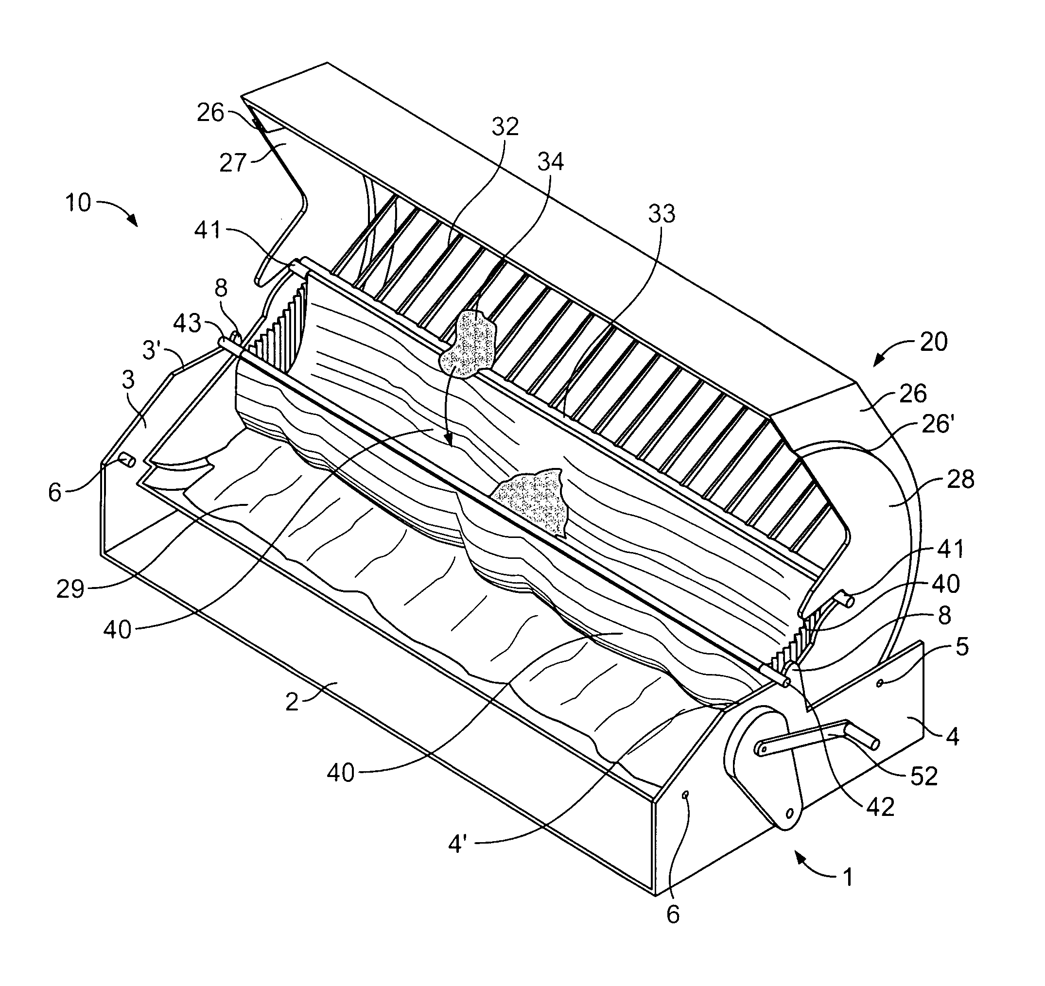
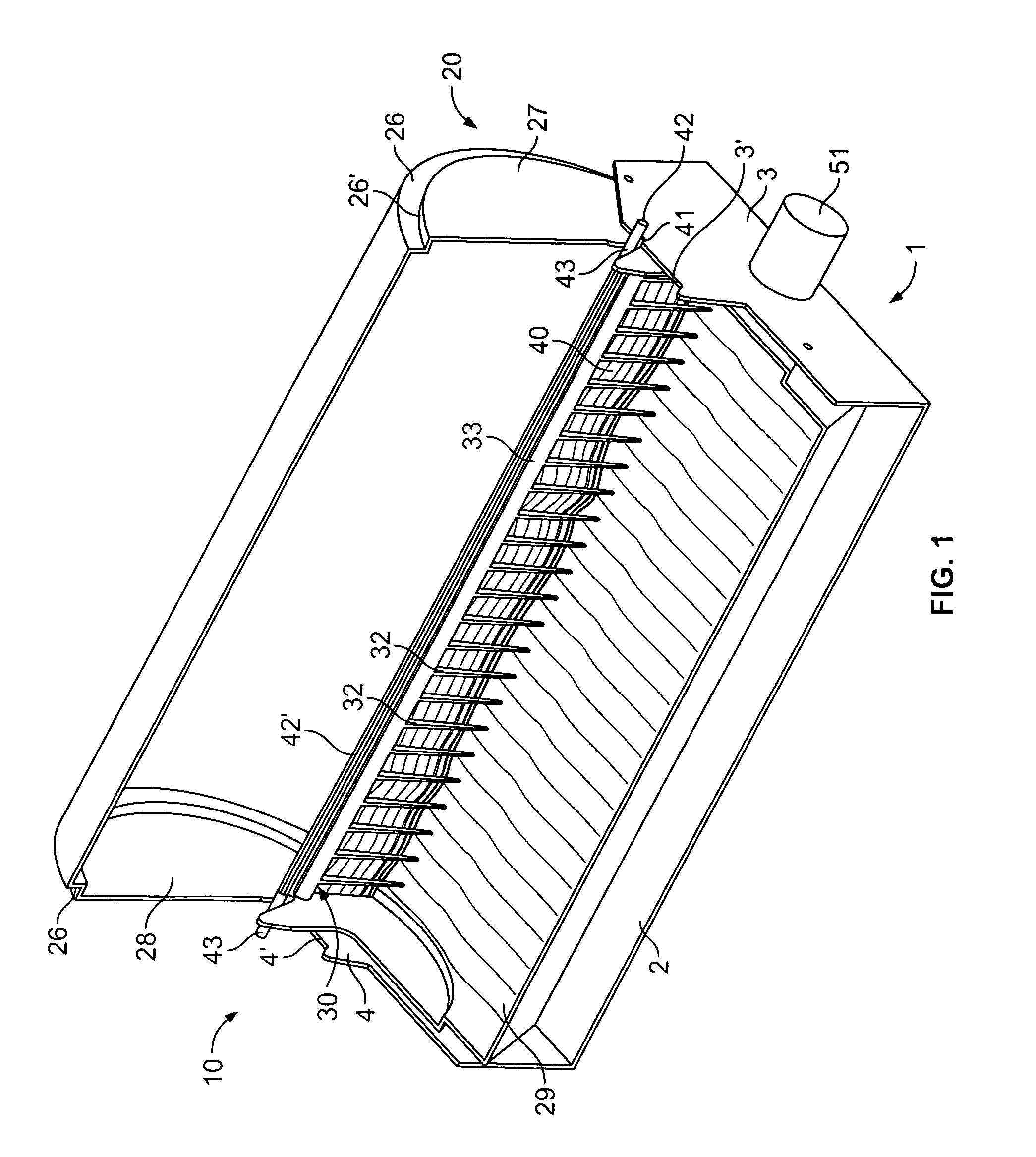
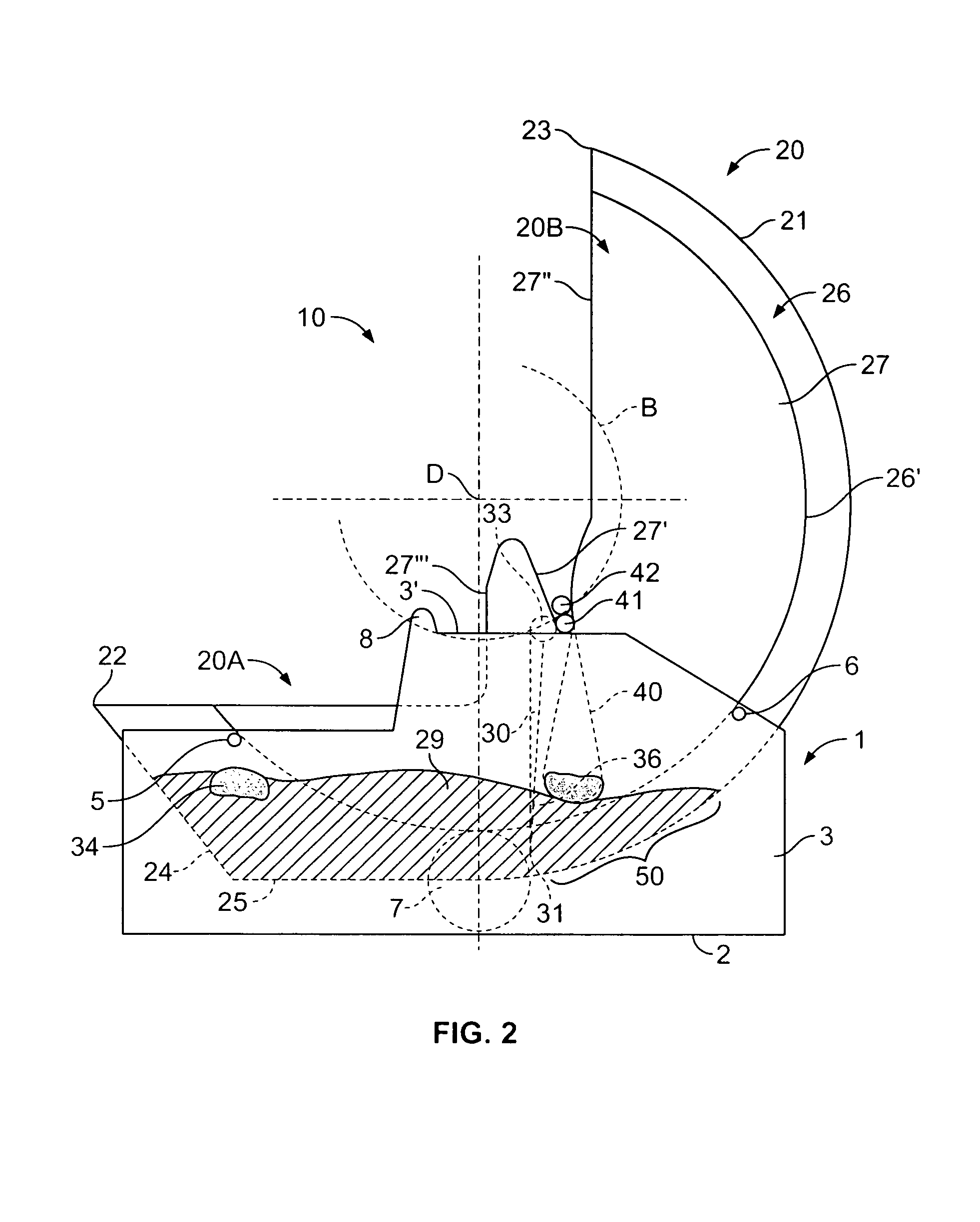
[0008]The task of the present invention is to create a cat
litter box which can be cleaned automatically or semi-automatically through a simple, cost-effective and low-maintenance construction, which has as high as possible a self-cleaning effect which because of an improved kinematic of the cleaning movement makes less demands on the
power output of the
drive motor, and which takes account of the needs of cats particularly for freedom of movement etc.
[0009]This and additional tasks are accomplished by the invention. In accordance with the invention, it is foreseen that the floor of the container consists of a closed half shell which extends over a span area of less than 250°, preferably over 135–230°, which, with a first part shell section, forms the floor of an essentially open collection tray and with the other part shell section, forms the rear wall of an interim storage container for the litter, whereby the cleaning mechanism at the transition segment is arranged between the part shell sections, whereby the storage chamber in the position of use is arranged on the side of the cleaning mechanism which points to the litter retention tray, and whereby the rotation of the container from the position of use is restricted to a pivoting angle of 120–180° in one direction. With the solution in accordance with the invention, a cat
litter box is therefore proposed which provides the cat with an open tray area for its use as a
toilet which is not covered by a roof or by an over-spanned ceiling, and which because of the rotatability, the displaced interim storage tray for the litter and the mechanical cleaning mechanism positioned between the open collection tray and the interim storage tray for the litter, can be cleaned by an automatic or semi-automatic swivel movement of the container. During a cleaning swivel movement, the cat litter is lead across the cleaning mechanism into the interim storage tray for the litter, whereby the waste matter is sieved out of or taken up from the cat litter at the cleaning mechanism. The entrance to the storage chamber, which is directly situated next to the cleaning mechanism, guarantees that the sieved-out waste matter travels the shortest possible distances to the cleaning mechanism, so that the abrasion of waste matter which could contaminate the cat litter is minimized. A further
advantage is that, because of the restricted swiveling movement and the tray sections arranged offset to each other, the relatively heavy cat litter is only moved and lifted up over a
short distance, so that a
drive motor of low power can be used.
[0010]In the preferred design, the collection tray and the interim storage tray for the litter are arranged roughly at right angles to one another, and intersect in a transition segment. This construction minimizes the volume required by the cat litter box, because the transition segment is both a component of the first partial shell section, which forms the collection tray, and a component of the partial shell section that forms the interim storage tray for the litter.
[0011]With the preferred method of construction in accordance with the invention, the entrance to the storage chamber is closed when in use, and can be automatically or manually opened during the cleaning movement. This design has the
advantage that there is no cause for concern with regard to the
odor inconveniences from the waste matter, which is sieved-out and contained in the
odor-tight closed storage chamber in the position of use. It is particularly preferable for this purpose if the storage chamber is constituted of flexible material, particularly of a bag or the like, and / or if the entrance to the storage chamber extends over the whole container width or the width of the cleaning mechanism. The use of a flexible bag makes it possible to dispense with closure flaps for the entrance to the storage chamber. Where the storage chamber extends across the whole width, centering guide plates or the like which could become soiled by the moving waste matter during the swivel movement are also unnecessary. As well as this, the flexible bag can be arranged in such a way that it extends as far as directly next to the cleaning mechanism, so that all areas of the cleaning chamber that come into contact with waste matter can be replaced when the bag is replaced.
[0012]A mechanically simple and cost-
effective solution for the openable and closable entrance is achieved in accordance with the invention by arranging two cross strips, which, in the position of use, lie one on top of the other, at the entrance to the flexible storage chamber. One of these strips is free and extends beyond the side pieces of the container, and the other can be moved together with the container. The side pieces of the container can then preferably possess a drive lug for the free cross strip and the upper sides of the side walls of the frame can form a guide path with a limit stop for the free cross strip, whereby the limit stop operates together with the free cross strip during the cleaning movement and accomplishes a relative movement between the free cross strip and the other cross strip which opens the entrance and whereby the drive lug positively returns the free cross strip to the starting position in a swivel movement in the opposite direction. In order to maximize the sealing effect at the entrance in the position of use, the free cross strip can preferably be raised from the guide path in the position of use of the cat litter box by means of the other cross strip. The solution described above in accordance with the invention accomplishes the opening and closing exclusively by positive forming and by gravity during the rotary movement.
[0013]Additionally suited to the purpose, the rotation of the container from the position of use is restricted to a pivoting angle of some 10–50° in the direction opposite to the swiveling up direction, so that the cat litter is again distributed essentially horizontally in the collection tray at the end of the cleaning process. In the simplest design of the cat litter box in accordance with the invention, the cleaning mechanism is formed by a cleaning rake with slit openings between cleaning struts. In accordance with the intention, the cleaning rake is then fastened in guides fitted to the interior walls of the side pieces from which it can be released, enabling it to be cleaned as the case arises or replaced with another cleaning rake. In addition, the interim storage tray for the litter and the interior wall of the collection tray can be well and simply cleaned when the cleaning rake is removed.


