
Reconfigurable optical add-drop multiplexers employing polarization diversity
a multi-layer, polarization-dependent technology, applied in the field of optical communication systems, can solve the problems of inherently difficult dynamic reconfiguration of the add-drop multiplexer, high cost of the current oadm, and inability to adapt to the changing needs of the user, so as to minimize the insertion loss and polarization-dependent loss.
- Summary
- Abstract
- Description
- Claims
- Application Information
AI Technical Summary
Benefits of technology
Problems solved by technology
Method used
Image

Examples
first embodiment
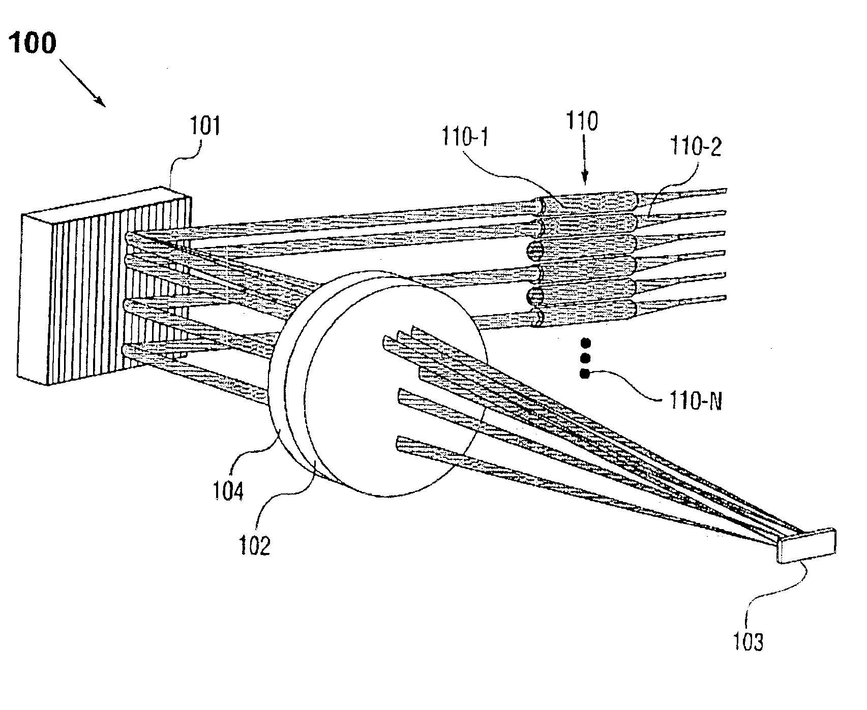
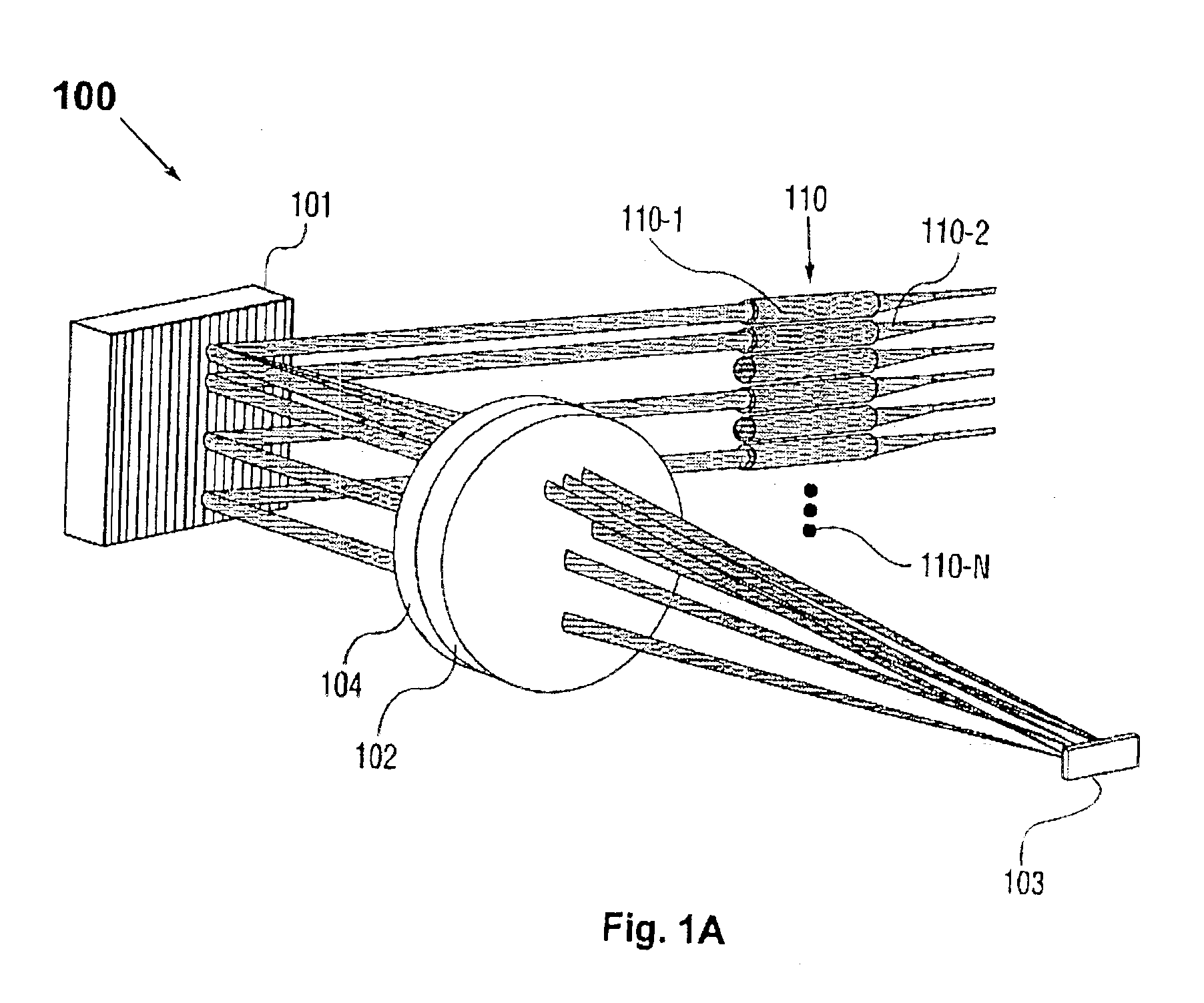
[0045]FIG. 1A depicts a wavelength-separating-routing (WSR) apparatus with which the invention may be employed. By way of example to illustrate the general principles and the topological structure of a wavelength-separating-routing (WSR) apparatus of the invention, the WSR apparatus 100 comprises multiple input / output ports which may be in the form of an array of fiber collimators 110, providing an input port 110-1 and a plurality of output ports 110-2 through 110-N (N≧3); a wavelength-separator which in one form may be a diffraction grating 101; a beam-focuser in the form of a focusing lens 102; and an array of channel micromirrors 103.
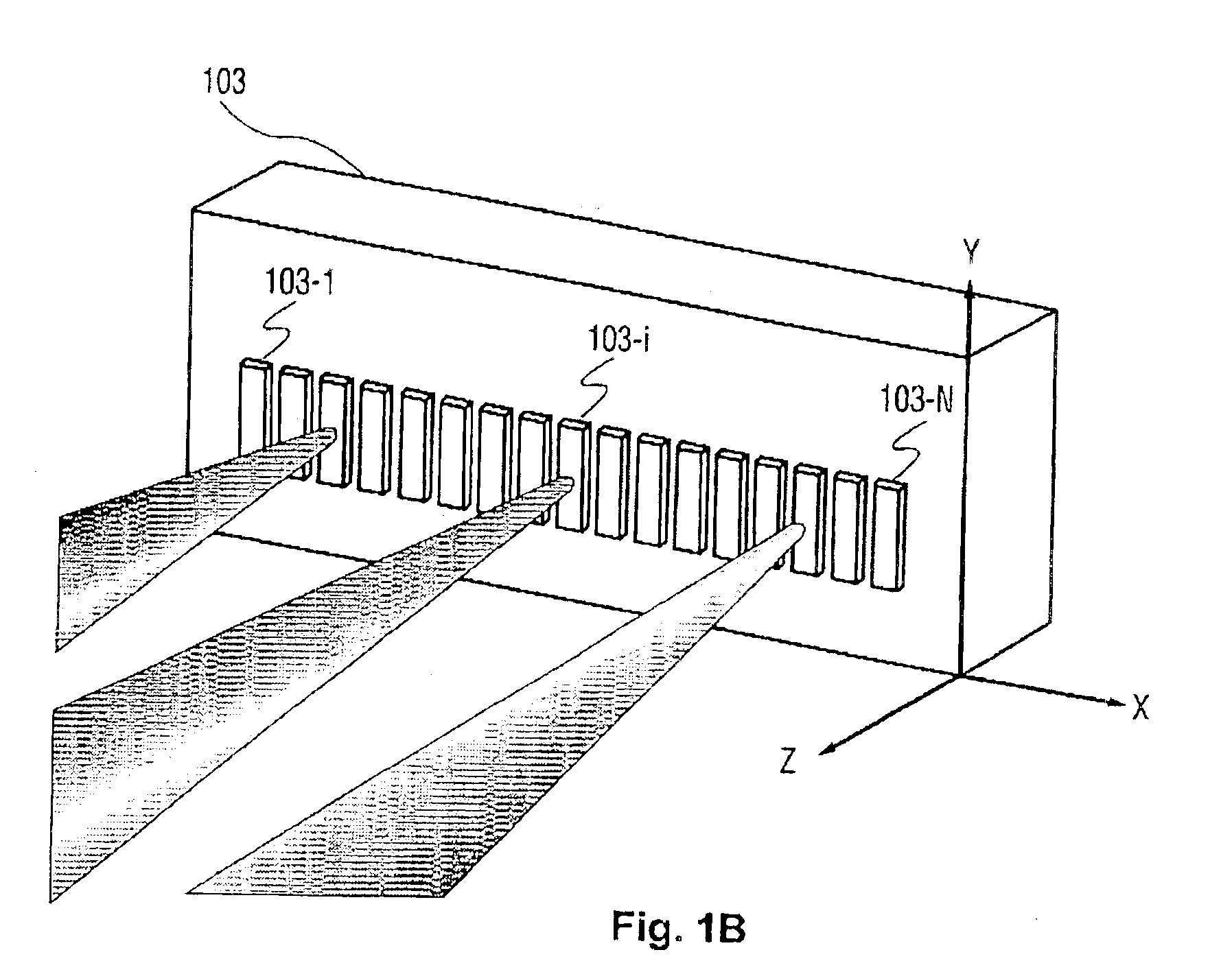
[0046]In operation, a multi-wavelength optical signal emerges from the input port collimator 110-1. The diffraction grating 101 angularly separates the multi-wavelength optical signal into multiple spectral channels, which are in turn focused by the focusing lens 102 into a spatial array of distinct spectral spots (not shown in FIG. 1A) in a one-to-o...
second embodiment
[0056]FIG. 2A depicts a WSR with which the invention may be used. By way of example, WSR apparatus 200 is built upon and hence shares a number of the elements used in the embodiment of FIG. 1A, as identified by those elements labeled with identical numerals. Moreover, a one-dimensional array 220 of collimator-alignment mirrors 220-1 through 220-N is optically interposed between the diffraction grating 101 and the fiber collimator array 110. The collimator-alignment mirror 220-1 is designated to correspond with the input port 110-1, for adjusting the alignment of the input multi-wavelength optical signal and therefore ensuring that the spectral channels impinge onto the corresponding channel micromirrors. The collimator-alignment mirrors 220-2 through 22-N are designated to the output ports 110-2 through 110-N in a one-to-one correspondence, serving to provide angular control of the collimated beams of the reflected spectral channels and thereby facilitating the coupling of the spect...
fourth embodiment
[0058]FIG. 3 shows a WSR apparatus with which the invention may be used. By way of example, WSR apparatus 300 is built upon and hence shares a number of the elements used in the embodiment of FIG. 2B, as identified by those elements labeled with identical numerals. In this case, the one-dimensional fiber collimator array 110 of FIG. 2B is replaced by a two-dimensional array 350 of fiber collimators, providing for an input-port and a plurality of output ports. Accordingly, the one-dimensional collimator-alignment mirror array 220 of FIG. 2B is replaced by a two-dimensional array 320 of collimator-alignment mirrors, and first and second one-dimensional arrays 260, 270 of imaging lenses of FIG. 2B are likewise replaced by first and second two-dimensional arrays 360, 370 of imaging lenses respectively. As in the case of the embodiment of FIG. 2B, the first and second two-dimensional arrays 360, 370 of imaging lenses are placed in a 4-f relay (or imaging) arrangement with respect to the ...
PUM
 Abstract
Description
Claims
Application Information