
Early coking detection in aircraft fuel

Active Publication Date: 2018-12-20
RAYTHEON TECH CORP
View PDF5 Cites 4 Cited by
  • Summary
  • Abstract
  • Description
  • Claims
  • Application Information

AI Technical Summary

Benefits of technology

The patent text describes a technical solution to improving the accuracy of a contamination detection sensor. The solution involves using an alternating current (AC) signal that matches the frequency of the sensor to minimize insertion loss. This can be in the form of a sinusoidal signal at the same frequency as the sensor. The technical effect of this solution is better accuracy in detecting contamination, which can help improve the efficiency and reliability of various applications that use the sensor.

Problems solved by technology

These carbon deposits (which have much lower thermal conductivity than typical heat exchanger surface materials and, hence, lower the heat exchangers' capability to conduct heat during this heat exchanger fouling) may lead to higher maintenance costs, more frequent repair / replacements of fuel-immersed components and ultimately, component failures.
In general, fuel system fouling inhibits efficient heat transfer which, in turn, results in higher component temperatures and potentially catastrophic component failures.
Autoxidation lowers the jet fuel's quality from the amount of gaseous oxygen dissolved into fuel which, in turn, lowers the fuel's thermal sink capabilities.
Other organic contaminants such as FAME (Fatty Acid Methyl Esters) that come from bio-diesel fuels and from cross-contamination during refueling of aircraft from ground-based fuel tankers / bowsers can also pose significant fuel quality problems.
The resulting carboxylic acids are corrosive to some metals and can increase the solubility of these metals in fuel.
Any fuel system components which consist of such metals are likely to be eroded and damaged.
Organic acids can increase carbon deposition in fuel and can have negative effect on the fuel's thermal stability and the fuel system's components' material compatibility.

Method used


Image

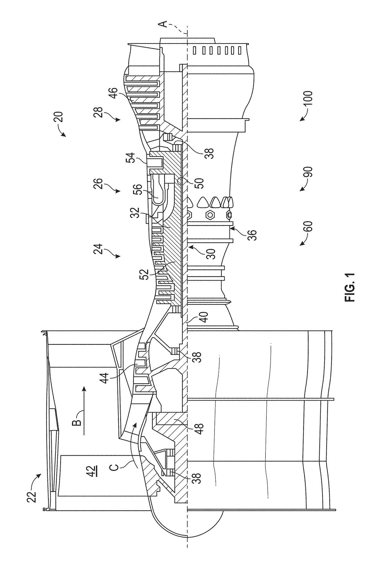
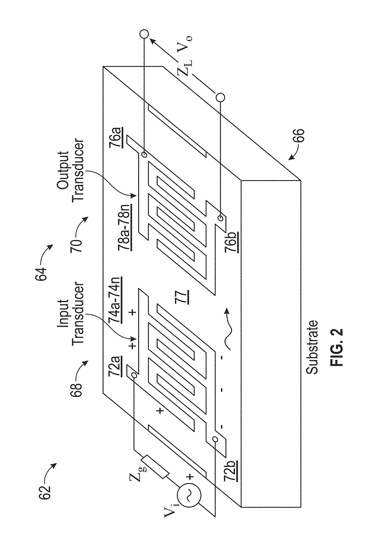
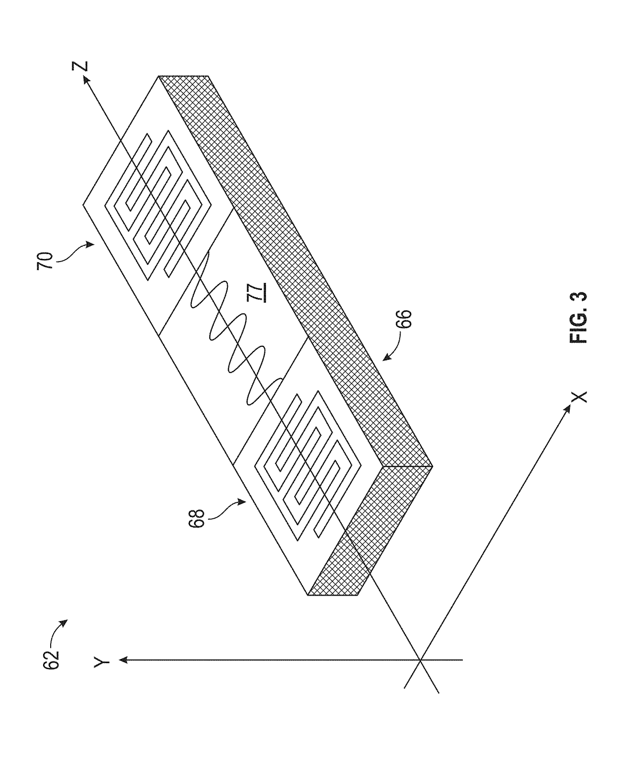
  • Early coking detection in aircraft fuel
  • Early coking detection in aircraft fuel
  • Early coking detection in aircraft fuel

Examples


Embodiment Construction

[0037]For the purposes of promoting an understanding of the principles of the present disclosure, reference will now be made to the embodiments illustrated in the drawings, and specific language will be used to describe the same. It will nevertheless be understood that no limitation of the scope of this disclosure is thereby intended. The following description is merely illustrative in nature and is not intended to limit the present disclosure, its application or uses. It should be understood that throughout the drawings, corresponding reference numerals indicate like or corresponding parts and features. As used herein, the term controller refers to processing circuitry that may include an application specific integrated circuit (ASIC), an electronic circuit, an electronic processor (shared, dedicated, or group) and memory that executes one or more software or firmware programs, a combinational logic circuit, and / or other suitable interfaces and components that provide the described...


PUM


Abstract

A system and method for detection of coking in a fuel. The system including a fuel system for delivery of fuel, a fuel contamination sensor having a contamination detection sensor with input and output transducers immersed in the fuel, a controller in operable communication with the fuel contamination sensor, the controller configured to execute a method for detection of coking in fuel. The method including generating an excitation signal for the contamination detection sensor, receiving at a controller operably connected to the contamination detection sensor, a sensor output signal from the output transducer, comparing the sensor output signal with the excitation signal, diagnosing a condition of the fuel based on a the comparing, and indicating a condition of coking based on the diagnosing. The system also includes an enunciator to indicate the detection of coking in the fuel.

Description

TECHNICAL FIELD[0001]The present disclosure relates generally to systems and methods for early detection of fuel degradation and fuel coking in a gas turbine engine. More specifically, the present disclosure relates to a method and apparatus for detection of degradation of aircraft fuel when operating at elevated temperatures.BACKGROUND[0002]Thermal stability of jet fuel is typically described in terms of the fuel's tendency to form deposits on fuel lines, valves, injectors, and combustion chamber surfaces in engines. These fuel system deposits can be created by two distinct free radical pathways: low temperature autoxidation (usually called fouling) and higher temperature pyrolysis (usually called coking or carbon deposition).[0003]Prolonged operation of gas turbine engines at elevated fuel temperatures (say, above 300° F. / 149° C.) accelerates the fuels reactions that lead to gum and carbon deposit accumulation on various fuel-immersed components such as: fuel filters (increasing t...

Claims


Application Information

Patent Timeline
IPC IPC(8): G01L9/00F01D17/02F02C7/22
CPCG01L9/0025F01D17/02F05D2260/80F05D2270/806F05D2220/32F02C7/222F05D2270/80F02C7/22G01N29/022G01N29/024G01N29/036G01N29/222G01N29/4436G01N2291/011G01N2291/012G01N2291/014G01N2291/0226G01N2291/02416G01N2291/0256G01N2291/0258G01N2291/0422G01N2291/0423G01N2291/0426G01N33/28
Inventor RIBAROV, LUBOMIR A.
Owner RAYTHEON TECH CORP
Learn More