Systems and Methods for Minimizing Insertion Loss in a Multi-Mode Communications System

a multi-mode communication and insertion loss technology, applied in the field of communication systems, can solve the problems of high production cost, bulkier packaging, high component count, etc., and achieve the effect of reducing insertion loss

Active Publication Date: 2013-03-14
PSEMI CORP
View PDF2 Cites 10 Cited by
  • Summary
  • Abstract
  • Description
  • Claims
  • Application Information

AI Technical Summary

Benefits of technology

[0009]According to a first aspect of the present disclosure, a method of minimizing insertion loss in at least one of two types of signals propagated through a communications system is provided. The method includes configuring a multifunctional filter to operate in a bandpass mode when a first type of signal is propagated through the multifunctional filter, and reconfiguring the multifunctional filter to operate in a lowpass mode when a second type of signal is propagated through the multifunctional filter, the lowpass mode providing a lower insertion loss upon the second type of signal than the bandpass mode.
[0010]According to a second aspect of the disclosure, a method of minimizing insertion loss in a duplexer is provided. The method includes configuring the duplexer to operate in a bandpass mode when a first type of signal is propagated through the duplexer, and reconfiguring the duplexer to operate in a lowpass mode when a second type of signal is propagated through the duplexer, the lowpass mode providing a lower insertion loss upon the second type of signal than the bandpass mode.
[0011]According to a third aspect of the disclosure, a communications system is provided. The system includes a multifunctional filter that is configurable to operate in a bandpass mode when a first type of signal is propagated through the multifunctional filter, and to operate in a lowpass mode when a second type of signal is propagated through the multifunctional filter, the lowpass mode providing a lower insertion loss to the second type of signal than the bandpass mode.

Problems solved by technology

However, as can be understood, such a configuration can lead to various undesirable issues such as higher component count, higher production cost, bulkier packaging, and increased power consumption.

Method used


Image

  • Systems and Methods for Minimizing Insertion Loss in a Multi-Mode Communications System
  • Systems and Methods for Minimizing Insertion Loss in a Multi-Mode Communications System
  • Systems and Methods for Minimizing Insertion Loss in a Multi-Mode Communications System

Examples


Embodiment Construction

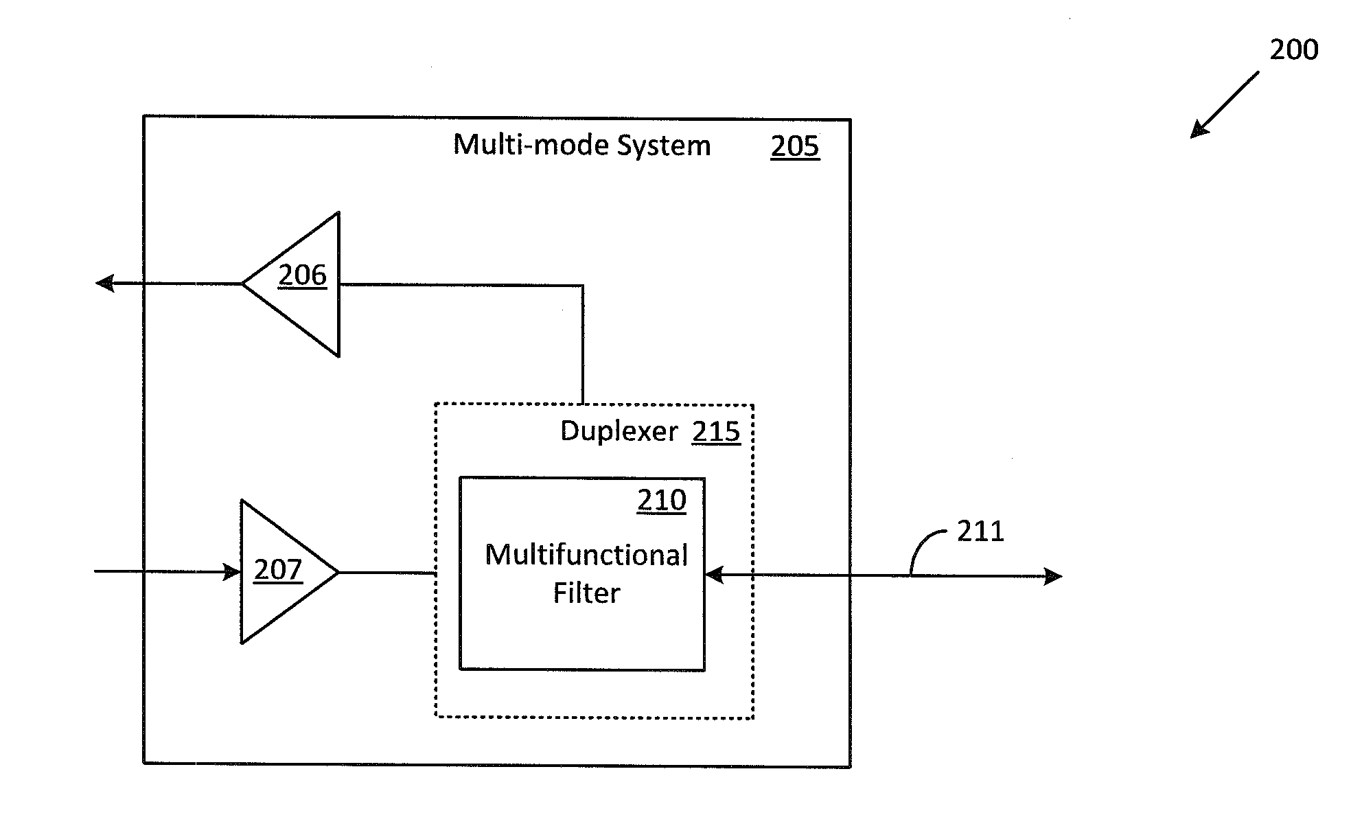
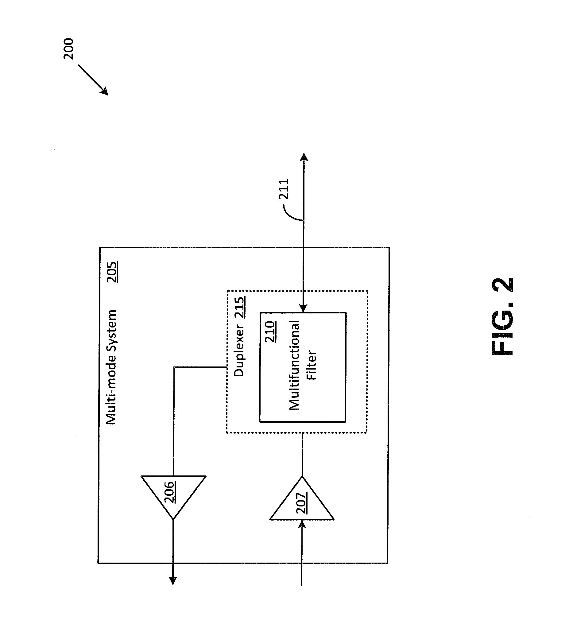
[0017]Throughout this description, embodiments and variations are described for the purpose of illustrating uses and implementations of the inventive concept. The illustrative description should be understood as presenting examples of the inventive concept, rather than as limiting the scope of the concept as disclosed herein. For example, it will be understood that terminology such as multifunctional, multimode, nodes, terminals, voltage drops, circuits, blocks, connections, lines, and coupling are used herein as a matter of convenience for description purposes and should not be interpreted literally in a narrow sense. Furthermore, the words “block” or “functional blocks” as used herein refer not only to a circuit containing discrete components or integrated circuits (ICs), but may also refer to various other elements such as a module, a submodule, or a mechanical assembly. Similarly, the word “line” as used herein may refer to various connectivity elements such as a wire, a cable, ...


PUM


Abstract

Methods and system for using a multifunctional filter to minimize insertion loss in a multimode communications system are described. Specifically described is a multifunctional filter that is configurable to operate in a bandpass mode when a first type of signal is propagated through the multifunctional filter, and to operate in a lowpass mode when a second type of signal is propagated through the multifunctional filter. The multifunctional filter presents a lower insertion loss to the second type of signal when operating in the lowpass mode than in the bandpass mode.

Description

FIELD[0001]The present teachings relate to communications systems. In particular, the present teachings relate to using a multifunctional filter for minimizing insertion loss in a multimode communications system.DESCRIPTION OF RELATED ART[0002]Multiband, multimode cellular phones are quite popular because of the convenience and flexibility provided by such devices, especially when a user of such a cellular phone travels between areas that are serviced by service providers using different signal propagation modes. Two of these signal propagation modes are referred to in the art as a time division duplex (TDD) mode and a frequency division duplex (FDD) mode.[0003]A cellular phone that is configured to selectably operate in either the TDD mode or the FDD mode, typically incorporates a first set of circuit elements that is optimized for TDD mode of operation and a second set of circuit elements that is optimized for FDD mode of operation. A switching mechanism is employed to cut out one...

Claims


Application Information

Patent Timeline
Patent Type & Authority Applications(United States)
IPC IPC(8): H04J3/10
CPCH03H7/0161H03H2210/036H04B1/406H03H7/465H04L5/14H03H7/0115H03H2007/013
Inventor NOBBE, DAN WILLIAM
Owner PSEMI CORP
Why Eureka
Try Eureka