
Downhole release joint

Inactive Publication Date: 2007-04-03
WELLBORE INTEGRITY SOLUTIONS LLC
View PDF18 Cites 8 Cited by
  • Summary
  • Abstract
  • Description
  • Claims
  • Application Information

AI Technical Summary

Benefits of technology

[0007]The present invention provides downhole apparatus comprising a first part connected to a second part by connecting means, the connecting means limiting axial and rotational movement of the first part relative to the second part and comprising a connecting member having a first end connected to said first part so as to limit axial and rotational movement of said first part relative to said first end and having a second end connected to said second part so as to limit axial and rotational movement of said second part relative to said second end, wherein the connecting member is provided between said first and second ends with a region of weakness in the connecting member provided by weakening means, and with means for minimising stress generated in the connecting means at said region of weakness when torque is transmitted in use between the first and second parts via the connecting member.
[0008]Thus, in use of downhole apparatus according to the present invention, the first part of the apparatus may be connected to a drill bit and a second part of the apparatus may be connected to a motor. Since the connection between the first and second parts is such as to limit axial and rotational movement of said parts relative to one another, the drill bit may be suspended from the motor by means of the apparatus as the drill bit is run downhole. Furthermore, torque may be transmitted from the motor to the drill bit via the apparatus during a drilling operation. In the event that the drill bit becomes jammed and rotational or axial movement of the remaining drill string is prevented, the drill string may be place in tension so that the connecting member breaks at said region of weakness. Although the drill bit remains jammed inhole, the remainder of the drill string may then be retrieved. The region of weakness is such that the drill bit may be released without the need to place the drill string under excessive tension. However, the region of weakness is not so weak that normal axial movement of the drill string cannot be undertaken without release of the drill bit. Despite the region of weakness in the connecting member, the apparatus of the present invention is capable of transmitting the high torques associated with drilling operations due to the means for minimising stress generated in the connecting member at the region of weakness.

Problems solved by technology

The region of weakness is such that the drill bit may be released without the need to place the drill string under excessive tension.
However, the region of weakness is not so weak that normal axial movement of the drill string cannot be undertaken without release of the drill bit.

Method used


Image

  • Downhole release joint
  • Downhole release joint
  • Downhole release joint

Examples


Embodiment Construction

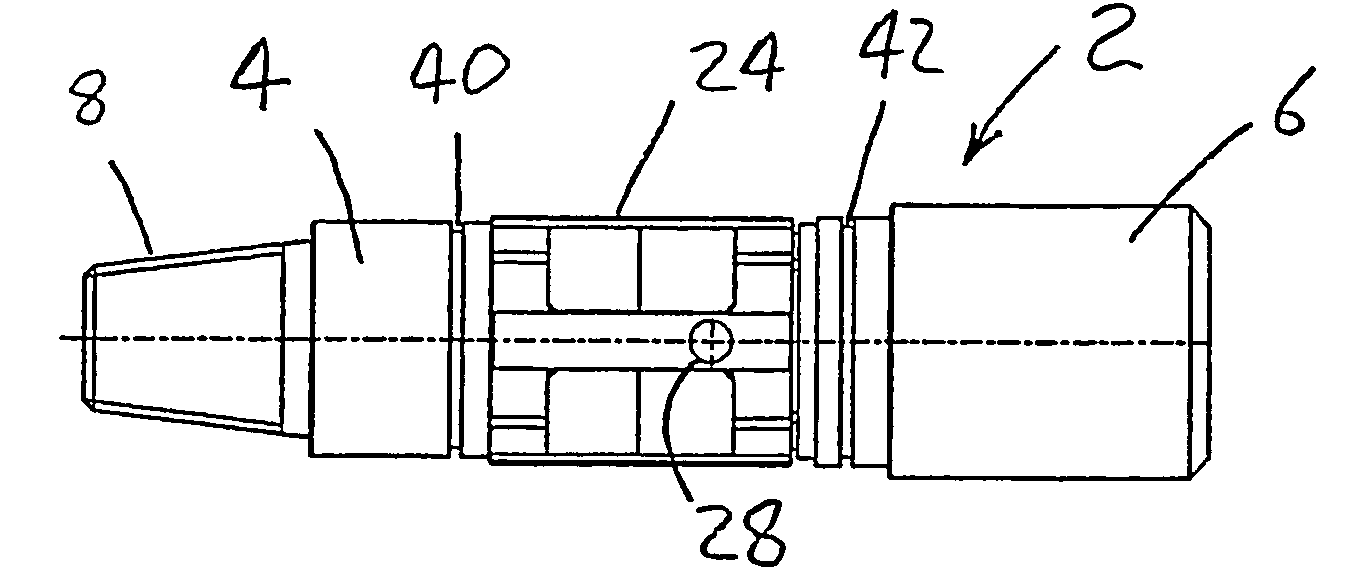
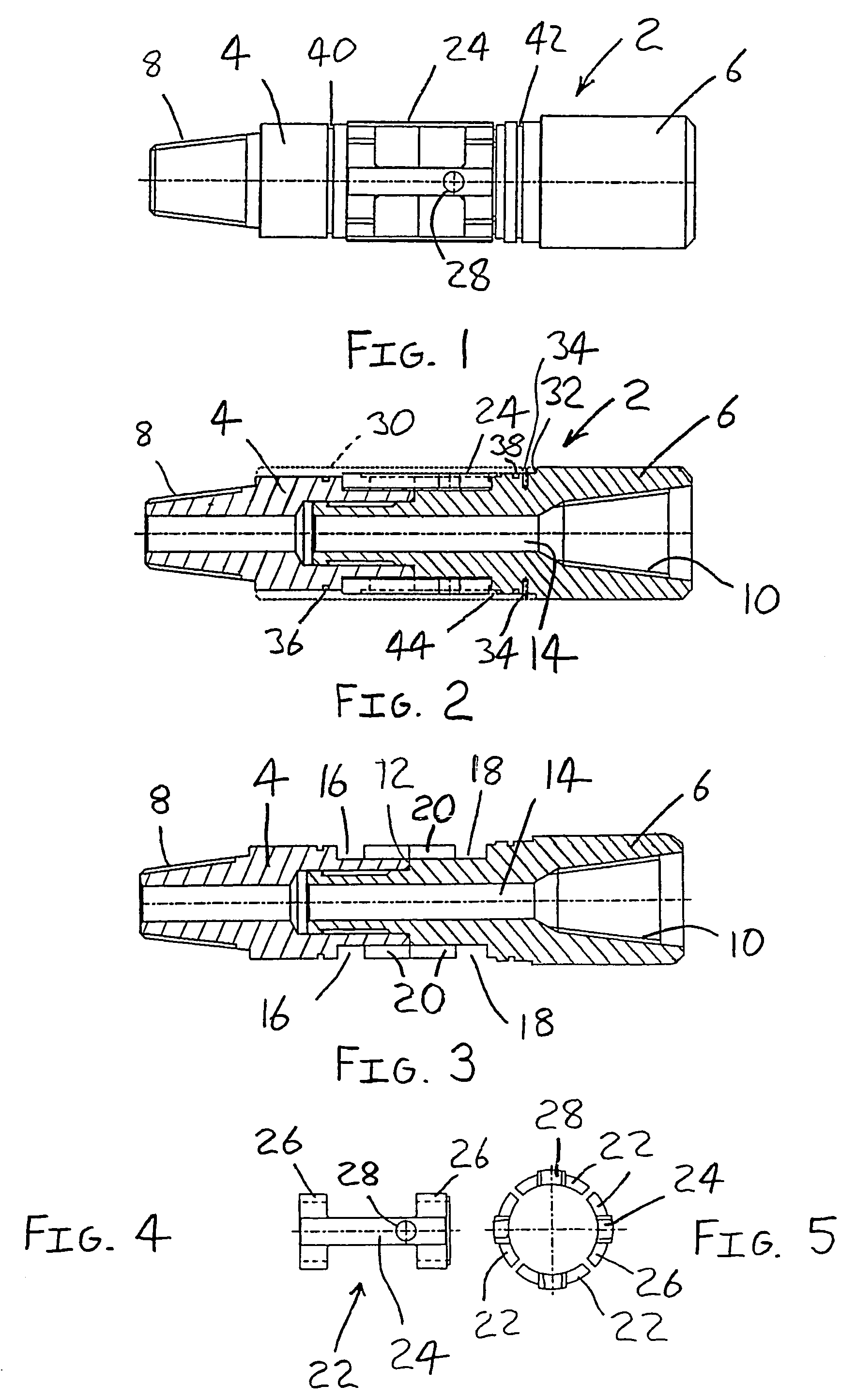
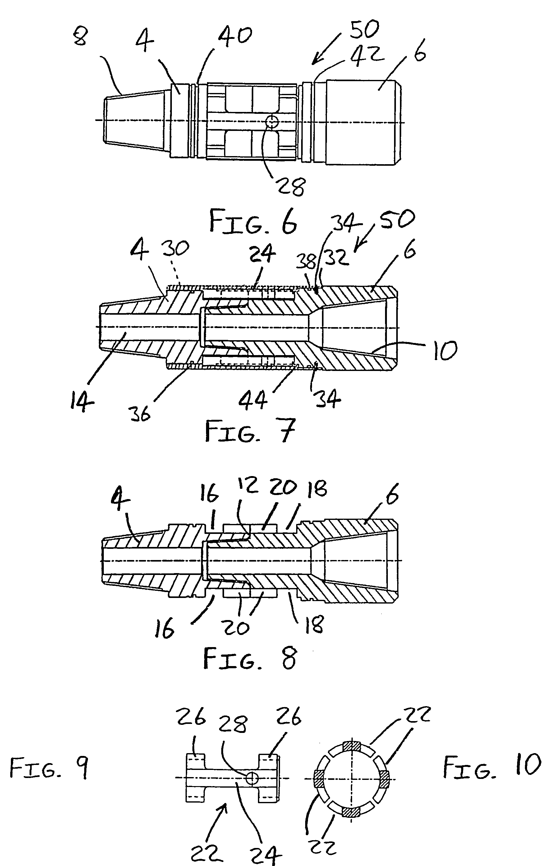
[0023]A first downhole release joint 2 is shown in FIGS. 1 and 2 of the accompanying drawings. The release joint 2 comprises first and second parts 4,6 which are each of a generally cylindrical shape of approximately the same external diameter. The first part 4 has an external screw thread 8 for engagement with downhole equipment such as a motor and the second part 6 has an internal screw thread 10 for engagement with downhole equipment such as a drill bit. The end of the second part 6 distal to the internal screw thread 10 has a reduced external diameter which locates within the end of the first part 4 distal to the external screw thread 8. The first part 4 abuts an annular external shoulder 12 defined on the external surface of the second part 6. The two parts 4,6 of the release joint 2 locate in abutment with one another so as to define a substantially cylindrical assembly having an axially projecting bore extending therethrough.

[0024]The external surface of each part 4,6 is prov...


PUM


Abstract

A downhole apparatus permitting separation of one part of downhole equipment from another part thereof includes a first part connected to a second part by a connecting member which limits axial and rotational movement of the first and second parts and has first and second ends connected respectively to the first and second parts. The connecting member includes a cross bar extending between the first and second ends having an aperture therein that results in a region of weakness, a portion of the cross bar spaced from the aperture minimizing stress at the region of weakness when torque is transmitted in use between the first and second parts via the connecting member.

Description

BACKGROUND OF THE INVENTION [0001]1. Field of the Invention[0002]The present invention relates to downhole apparatus permitting separation of one part of downhole equipment from another part thereof.[0003]2. The Prior Art[0004]It is not uncommon for a drill bit to become stuck inhole during downhole oil and gas drilling operations. In order to allow retrieval of a downhole drill string when a drill bit becomes jammed, it is known to provide a drill string with an emergency release joint immediately uphole of the drill bit. During normal operation, the release joint transmits torque from a motor to the drill bit. However, in the event that the drill bit becomes jammed to the extent that axial and rotational movement of the drill bit is not possible, the drill bit may be separated from the remainder of the drill string by virtue of the release joint. The remainder of the drill string may then be moved axially uphole so that specialist retrieving equipment may be run to the drill bit i...

Claims


Application Information

Patent Timeline
IPC IPC(8): E21B17/06E21B17/04
CPCE21B17/04E21B17/06
Inventor MCGARIAN, BRUCEGILLIES, IAN ALEXANDER
Owner WELLBORE INTEGRITY SOLUTIONS LLC
Learn More