Feedback parameter estimation for electric machines

a technology of electric machines and feedback parameters, which is applied in the direction of computer control, dynamo-electric motors/converters, program control, etc., can solve the problems of affecting the operation of the motor, affecting the performance of the power steering system, and not always being able to address the varied operating conditions of the motor

Inactive Publication Date: 2007-04-03
GM GLOBAL TECH OPERATIONS LLC +1
View PDF116 Cites 54 Cited by
  • Summary
  • Abstract
  • Description
  • Claims
  • Application Information

AI Technical Summary

Benefits of technology

[0006]A method for estimating a parameter of an electric machine, comprising: receiving at least one of a torque command signal indicative of a desired torque for the electric machine and a current value. The parameter estimating is a resultant of a parameter estimation process responsive to one or more of the torque command signal and the current value.

Problems solved by technology

Therefore, without some form of temperature, build, or duration / life dependent compensation, the variations in motor output torque and system damping will result in decreased performance of the power steering system.
While able to correct for variations in resistance R due to temperature, build, and life, and well suited for its intended purposes, the correction scheme disclosed in that invention was not always capable of addressing varied motor operating conditions.
In a vehicle employing an electronic steering system significant time may be spent at stall and low motor currents (highway driving for example), and large changes in temperature may occur during these periods.
Most correction schemes are configured to make corrections very slowly, thus, it may require significant time to eliminate such an error.
Of further significance, existing design schemes may not account for variation in other motor parameters, such as motor constant, which may vary significantly over temperature, build, and life.
However, there are also other motor designs in existence that, for cost purposes, require the use of a voltage mode controlled system.
In such a situation, the same methods described above to compensate for temperature in the current controlled motor cannot be applied to the voltage-controlled motor in a cost effective manner.

Method used


Image

  • Feedback parameter estimation for electric machines
  • Feedback parameter estimation for electric machines
  • Feedback parameter estimation for electric machines

Examples


Embodiment Construction

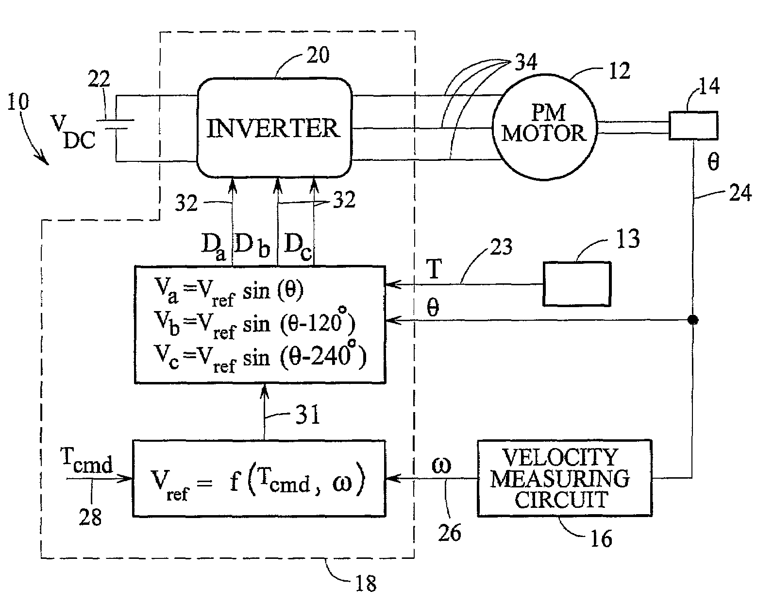
[0022]In many practical applications of motor control, such as electronic power steering systems, it is often the case that cost and design considerations prohibit the use of temperature sensors placed directly on the motor windings or the magnets. However, such data is used to maintain motor torque accuracy over temperature, build, and life variations of the key parameters in a voltage mode controlled system. To insure adequate torque control and operation of a motor in an electronic power steering system it has become desirable to compensate the control of the motor for variations in motor parameters such as, but not limited to, motor resistance R, and motor constant Ke as a function of temperature, build, and life. In a motor control system, a motor employing voltage mode control is controlled via an applied motor voltage, not the motor current. However the torque produced by the motor is proportional to the motor current. Therefore, variations of the motor parameters such as tho...


PUM

PropertyMeasurementUnit
temperatureaaaaaaaaaa
frequencyaaaaaaaaaa
frequencyaaaaaaaaaa

Abstract

A method and system for estimating a parameter of an electric machine, including a controller and a switching device, the controller executes a parameter estimation process, which is responsive to at least one of: a current value and a torque command and the resultant of the parameter estimation process representing an estimated parameter of the electric machine. The parameter estimation includes a method for estimating a temperature of the electric machine comprising: a temperature sensor operatively connected to and transmitting a temperature signal corresponding to a measured temperature to a controller, which executes a temperature estimation process responsive to a temperature signal from a temperature sensor.

Description

CROSS-REFERENCE TO RELATED APPLICATIONS[0001]This application claims the benefit of U.S. provisional application No. 60 / 313,302 filed Aug. 17, 2001 the contents of which are incorporated by reference herein in their entirety.BACKGROUND[0002]Electric machines, for example, permanent magnet (PM) motors as may be employed in electric power steering systems (EPS) are affected by parameter variations, which impact the overall system performance as a function of temperature, build and changes over life. The motor circuit resistance, R; inductance, L; and the motor torque / voltage constant, Ke; are the three primary parameters, which affect motor control and performance. Over normal operating temperatures, the motor circuit resistance, R changes by up to 60 to 70%; the motor inductance, L varies a modest amount; and the motor constant, Ke varies by as much as + / −7%. In addition, both the motor circuit resistance, R and motor constant, Ke exhibit variations of about + / −5% for build and a deg...

Claims


Application Information

Patent Timeline
Patent Type & Authority Patents(United States)
IPC IPC(8): H02P23/00H02P25/00H02P27/00G05B13/02B62D5/04G01K7/21G05B13/04G05B23/02H02P6/08H02P21/14H02P23/14H02P29/00
CPCB60L11/14B60L15/025B62D5/0496G01K7/21G05B13/042G05B17/02H02P23/14H02P29/0055H02P29/0066H02P29/0088B60L11/1803Y02T10/70B60L2260/56Y02T10/643Y02T10/7005Y02T10/7077B60L50/16B60L50/51H02P29/64H02P29/68H02P29/662Y02T10/64Y02T10/7072
Inventor KLEINAU, JULIE A.COLLIER-HALLMAN, STEVEN J.CHANDY, ASHOKPATANKAR, RAVINDRA P.
Owner GM GLOBAL TECH OPERATIONS LLC
Why Eureka
Try Eureka