Decoding apparatus and decoding method

a technology of decoding apparatus and decoding method, which is applied in the direction of digital signal error detection/correction, instruments, recording signal processing, etc., can solve the problems of complex circuits required to specify the bit length during error correction, and the inability to detect the continuous bit errors contained in the odd-numbered bit, so as to improve the decoding characteristic

Inactive Publication Date: 2007-04-03
HITACHI GLOBAL STORAGE TECH JAPAN LTD
View PDF10 Cites 6 Cited by
  • Summary
  • Abstract
  • Description
  • Claims
  • Application Information

AI Technical Summary

Benefits of technology

[0027]As a consequence, an object of the present invention is to reduce an occurrence of such an error event which cannot be detected while an error is corrected.
[0028]To solve the above-described problems, a coding method according to the present invention is featured by that while a parity bit capable of detecting an error during reproducing operation is generated, a coding operation is carried out in such a manner that a specific pattern is not contained in a code word series to which this parity bit is added. At the same time, a coding apparatus of the present invention is arranged by that while a most likelihood path is searched based upon the Viterbi algorithm, such a transition path is not selected during the path searching stage. This transition path corresponds to a specific pattern which has been removed from the code word series by the coding operation. As a consequence, for example, if the specific pattern corresponds to “1111”, then it is possible to avoid an occurrence of more than 4-bit continuous errors in the decoding errors. Since this coding arrangement is combined with the error detection / correction, the decoding characteristic can be improved.

Problems solved by technology

However, as to the more than 4-bit continuous errors corresponding to the subsequent event errors having the short distances, the odd-numbered bit continuous bit errors contained therein cannot be detected.
There is another problem that also as to the detectable odd-numbered bit error, the circuit required to specify this bit length during the error correction becomes complex.

Method used


Image

  • Decoding apparatus and decoding method
  • Decoding apparatus and decoding method
  • Decoding apparatus and decoding method

Examples


second embodiment

[0080]Referring now to FIG. 13 and FIG. 14, a second embodiment mode of the present invention will now be described.

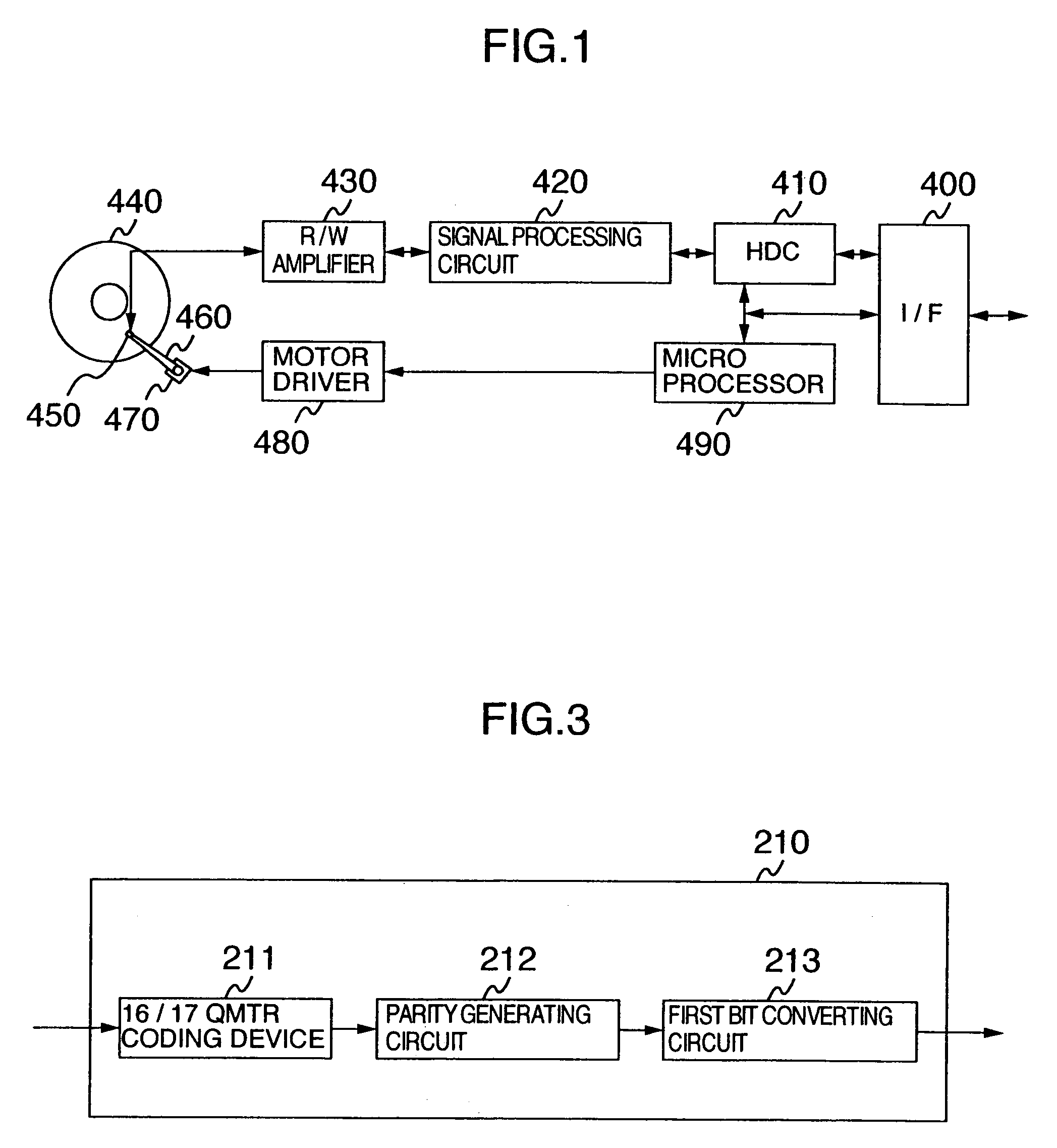
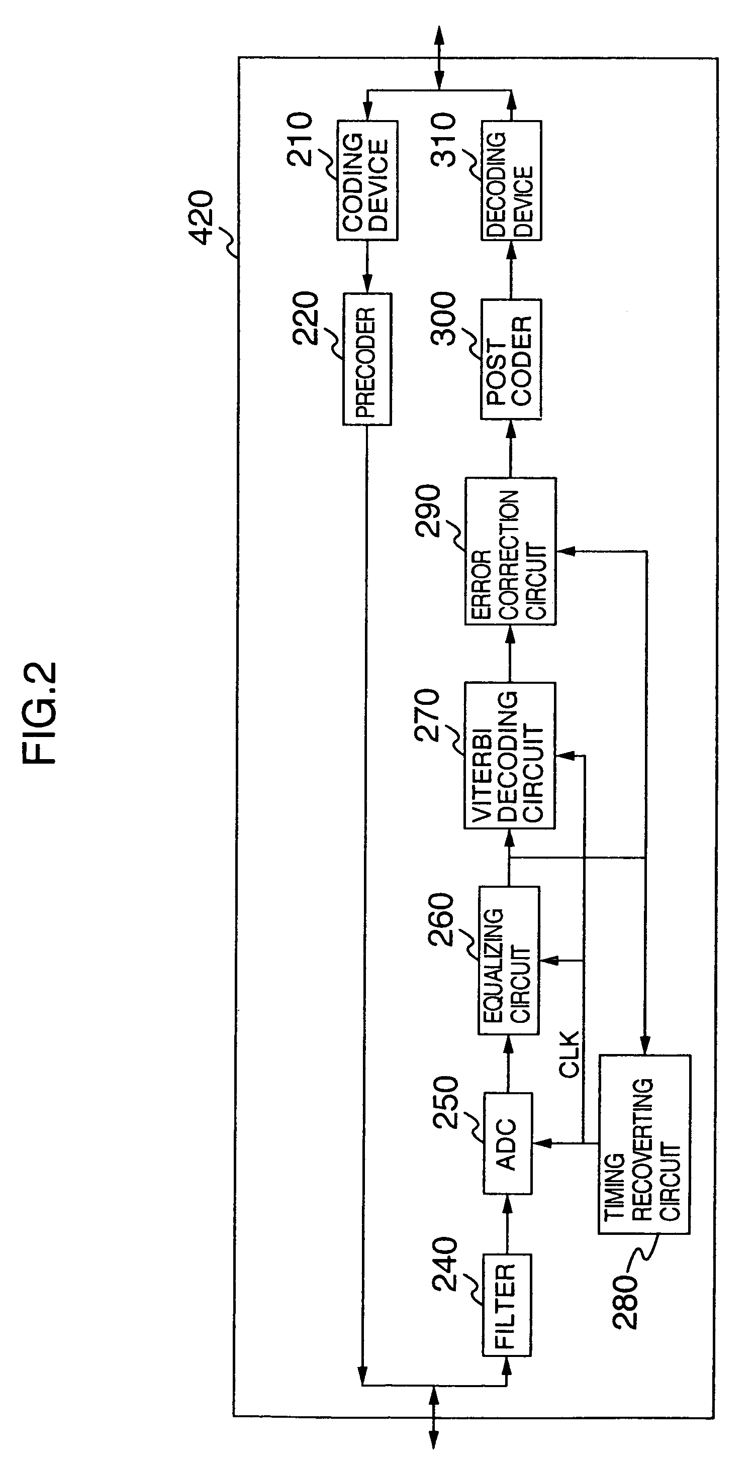
[0081]A basic arrangement of the second embodiment mode is similar to that of the first embodiment mode. However, this second embodiment mode owns a different technical aspect as to a coding method of recorded data, a most likelihood decoding method of reproduced data, and a decoding method. As a consequence, the coding device 210, the decoding device 310, and the Viterbi decoding circuit 270 indicated in FIG. 2 are replaced by a coding device 350, a decoding device 370 (not shown), and a Viterbi decoding circuit 360 (not shown). Now, this different technical aspect of the second embodiment mode will be mainly explained.

[0082]FIG. 13 represents an internal arrangement of the coding device 350 employed in a signal processing circuit according to this embodiment mode. The coding device 350 is arranged by a 24 / 25 QMTR coding device 351, a parity generating circuit 212, an...

first embodiment

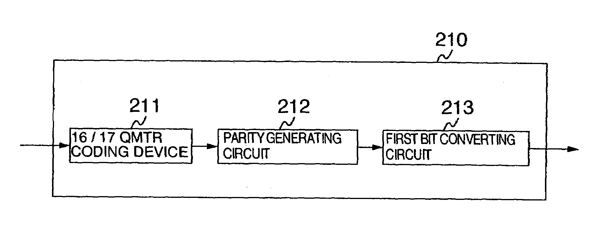
[0093]A parity generating circuit 212 shown in FIG. 13 may use such a parity generating circuit employed in the above-explained coding device 210 shown in FIG. 3. As previously described in the first embodiment, there is such a case that since the parity bit generated in the parity generating circuit 212 is added to the code word, the continuous length of 1 is increased. This condition may be similarly applied to another continuous length of 0 and a continuous length of a catastrophe series.

[0094]The first bit converting circuit 353 performs a process operation capable of avoiding a breach of a coding restriction, which is caused by adding such a parity bit. This first bit converting circuit 353 judges as to whether or not the breach of the coding restriction occurs by checking the parity bit and several bits located before / after this parity bit. If the breach of this coding restriction occurs, then the first bit converting circuit 353 converts the bit stream in order to follow the ...


PUM

PropertyMeasurementUnit
frequencyaaaaaaaaaa
magneticaaaaaaaaaa
magnetizationaaaaaaaaaa

Abstract

In a coding method which does not restrict a run length of “1” while data is recorded / reproduced, there are such a drawback that when an error correction is carried out, a total number of error data to be corrected is increased, and also errors of not-detectable data are increased. While data is coded, a continuous number of “1” contained in a code word is limited, and then an error correction is carried out inside a coding / decoding process operation. Thus, a recording / reproducing apparatus having a small number of decoding errors is available.

Description

CROSS-REFERENCE TO RELATED APPLICATIONS[0001]This application is a continuation of application Ser. No. 09 / 986,597 filed on Nov. 9, 2001 now U.S. Pat. No. 6,704,154, which is a continuation of application Ser. No. 09 / 502,056 filed on Feb. 10, 2000, now U.S. Pat. No. 6,335,841. The contents of application Ser. Nos. 09 / 986,597 and 09 / 502,056 are hereby incorporated herein by reference in their entirety.BACKGROUND OF THE INVENTION[0002]The present invention is related to an apparatus for coding data to record coded data on a recording / reproducing apparatus for reproducing and decoding the recorded data. More specifically, the present invention is directed to a method for coding and decoding data.[0003]To understand the present invention, the conventional technique will be briefly explained. The conventional technique involves explanations about the Viterbi algorithm and trellis representation, the partial response channel, and the error correction.[0004]The Viterbi algorithm is to dete...

Claims


Application Information

Patent Timeline
Patent Type & Authority Patents(United States)
IPC IPC(8): G11B5/09G11B5/012G11B20/10G11B20/18H03M5/14H03M7/14H03M13/31H03M13/41
CPCG11B20/1833H03M5/145H03M13/31G11B5/012G11B5/09G11B20/10009
Inventor HIRANO, AKIHIKOMITA, SEIICHIWATANABE, YOSHIJU
Owner HITACHI GLOBAL STORAGE TECH JAPAN LTD
Why Eureka
Try Eureka